2013-07-11 16:12 UTC
I have always been fascinated by early microcomputers. Ever since I painfully wrote my first machine code program on the 6502 based
KIM-1 I have been hooked by these simple and lucid computers. I have constructed various designs in the past and this article is about my latest computer. The first one with some form of name actually.
I call it the
MC3 since it is a
Micro
Computer based on the HD630
3 microprocessor :) The HD6303 is a variant of the Motorola MC6803 and is produced by Hitachi. The 6803/6303 is software compatible with the 6800 but contain on-board RAM, timer, serial interface, clock circuit and an improved instruction set. It's a lot of old fashion micro computing on a single chip and the HD6303 is still widely available on eBay to this date.
Edit: Another good source for 65xx/68xx might be www.unicornelectronics.com
The reason for basing my design on the 6800 family rather than the more community friendly 6502 family is that I already have enough 6502 computers and I really like the structure of the 6800. Having a 16-bit stack pointer and index register is actually great. The 6801 improved the instruction set of the 6800 quite a bit and the 6303 improves it even further with functions such as the XGDX (exchange D and X registers).
The MC3 is a small microcomputer that fits on a single 100x160mm board. It is my own design and the intention is that it should be able to run programs (with some modifications) made for the SWTPC6800, EXORciser or other similar computers. It should also be easy to interface to a modern PC for cross-development.
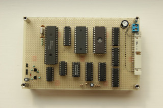
This is an image of the CPU board also containing RAM, ROM, address decoding, serial console interface and bus drivers. It's a complete computer! As you see there is not that many components needed for a fully functioning system. For the bus connection I used a standard 40-pin flat-cable connector. The same connector used for IDE hard drives. It is simple, cheap, widely available and has enough pins for my bus.
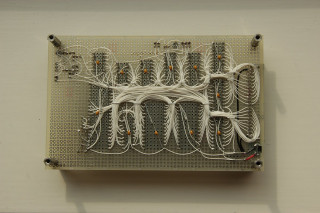
The back side view of the CPU board. I did not use wire-wrap this time as I did with my earlier designs. This board has been soldered. The main reason is that it is getting harder and harder to obtain wire-wrap supplies these days. I was also quite certain that I would not have to make many changes to the design. Soldering this way also makes the board much lighter and thinner than if it was wire-wrapped.
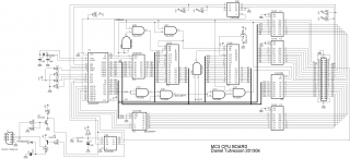
This is the final schematic of the MC3 CPU board. Power supply is not included in the schematic. 100nF decoupling capacitors over every chips power supply are also present but not drawn (don't forget these!). Also all logic chips are HCT variants regarding of what the schematic says. I just did not have the correct symbols. All external connections are buffered. These CPU's are not manufactured anymore. Better be careful.
Specifications
- HD63A03RP CPU @ 1.2288MHz (4.9152MHz external crystal divided by four)
- 32 kB RAM
- 16 kB ROM
- 128 kB addressable I/O space divided into eight 16 kB banks
- 16-bit timer
- RS232 console interface, 9600bps 8N1
Memory map
$0000-$001F --- 6303 internal registers (timer, serial interface etc)
$0020-$7FFF --- RAM
$8000-$BFFF --- 16k*8 decoded external I/O
$C000-$FFFF --- ROM
There is also the 6303 built-in RAM placed at $0080-$00FF shadowing the external RAM and can be enabled/disabled when needed using the 6803 RAM control register at $0014.
Selecting I/O bank
Which one of the eight I/O banks that should show up at $8000-$BFFF is selected by writing to the bank select register at $0002. This is the built in 8-bit port (pins P10-P17) of the 6303 which I use for this purpose.
- Bit 0-2 selects bank 0-7. These three pins are directly connected to IC8.
- Bit 3-6 are not used
- Bit 7 enables/disables interrupts from the bus. "0" enables bus interrupts and "1" masks bus interrupts. This is realized using IC6B.
Bus interface
All lines are buffered on the CPU board through '245 and '244 buffers. It makes it a little more complex and takes more chips but it's a good protection.
D0-D7 --- Data bus.
A0-A13 --- Address bus.
S0-S7 --- I/O select pins. Active low. One for each page.
R/W --- Read/Write signal. Motorola standard. High equals read and low equals write.
E --- System clock. Motorola standard. Address and data lines are valid when E is high.
IRQ --- Active low with pull-up.
NMI --- Active low with pull-up.
RES --- Active low reset signal.
ROM and monitor program
The 16 kB ROM area is actually a 27256 32 kB ROM that is divided in two. A14 is hardwired and divides the ROM in two halves. The high part and the low part. Which makes it possible to have two different monitor programs in ROM and selectable by pulling A14 high or low.
I have written a monitor program that has the most basic functionality such as examining and changing memory byte by byte, dumping memory to console page by page, alter the stack contents and uploading S19 data over the console.
> h

MC3 monitor 1.1
Daniel Tufvesson 2013

 G  Go (RTI)
 J  Jump to address
 L  Load S19 from console
 MC Memory change
 MD Memory dump
 RR Print contents of stack
 RS Reset stack pointer
 RC Change stack CC
 RA Change stack A
 RB Change stack B
 RX Change stack X
 RP Change stack PC
 P  Select I/O page

> md 0000

ADDR  0  1  2  3  4  5  6  7   8  9  A  B  C  D  E  F
0000  FF FF 87 4A 51 49 54 B2  60 86 9D FF FF 00 00 CA  ...JQIT.`.......
0010  FF 0A 30 FF 3F FF FF FF  FF FF FF FF FF FF FF FF  ..0.?...........
0020  80 00 BF FF FF 55 BF FF  9F FE 95 2C 05 54 05 4C  .....U.....,.T.L
0030  9A 65 50 CA 8A 20 25 E0  8E C5 82 23 A8 80 55 43  .eP.. %....#..UC
0040  04 4E A4 FB 25 50 6B E8  B6 CC 60 48 4C CB 57 58  .N..%Pk...`HL.WX
0050  80 AB 62 9E 4A F3 14 90  64 64 53 D9 EA 04 04 23  ..b.J...ddS....#
0060  5B 0A 61 92 9A 26 CD 45  54 08 12 18 48 29 97 94  [.a..&.ET...H)..
0070  50 42 23 00 98 02 0A 65  61 80 C6 0C C6 16 00 D3  PB#....ea.......
0080  7E 00 87 C7 60 81 F1 8E  00 7F CE 80 00 00 2A A7  ~...`.........*.
0090  00 08 8C BF FF 26 F6 CE  80 00 8D 1D A8 00 26 22  .....&........&"
00A0  08 8C BF FF 20 07 0D 0A  2A 20 04 00 87 00 EB 86  .... ...* ......
00B0  2B BD C0 03 7C 00 83 20  CE DF 85 00 85 00 86 9B  +...|.. ........
00C0  83 39 97 84 CE 00 A6 BD  C0 00 CE 00 83 BD C0 12  .9..............
00D0  BD C0 12 BD C0 15 DE 85  20 C6 60 16 EC AB AA C0  ........ .`.....
00E0  28 AD A8 46 17 A8 01 15  60 0C 11 00 1A 04 AA 01  (..F....`.......
00F0  FF C2 54 8F 81 6C 15 0A  47 D9 A5 C0 47 50 80 FF  ..T..l..G...GP..

>
Printout of the help command and a dump of the zero-page
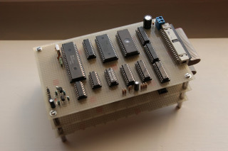
View of the MC3 system with CPU board on top and two expansion boards underneath.
by Tom LeMense 2013-09-22 15:04 UTC
Hi! What a coincidence - I am in the process of making my own HD6303Y singleboard computer, for about the same reasons as yours. I was in the middle of porting a 68HC11 ROM monitor to the HD6303 when I found your site. I'll still complete the port but it's nice to have a "plan B" if/when my port doesn't work.
My specs: HD63B03Y @ 1.8MHz, 64K of RAM, 16K of ROM (banks over upper RAM), FTDI UART-to-USB bridge, RTC7301 realtime clock, Z8536 CIO, and SD-card interface on port 6.
I'm happy to share anything of mine with you, if you're interested (schematics, PCB layout, whatever).
I'm curious to know what tools you use for code development. It's a bit painful under windows as the tools I'm using are DOS based (so I run them in DOSbox).
cheers!
-tom
by daniel 2013-09-27 08:13 UTC
Hi Tom! That's really fun to hear. I'm glad that someone else is building new things for the 6303. It's a nice CPU. Feel free to use the material I provide on my site.
I would absolutely like to share some ideas and have a look at what you have done. The SD-card interface sounds interesting. Do you have any code written for it yet?
I do all my cross-development under Linux using the Emacs editor and an ancient old-school open source assembler. No fancy stuff like macros :)
by Tom 2013-09-29 19:57 UTC
Hi Daniel! No code written yet for anything - I'm doing a bit of prep-work while waiting for my PCBs to arrive from OSHpark - mostly hacking on your MONITOR program a bit (goal is to include a disassembler).
I'm planning on working with the old DOS tools in a DOSbox VM under Win7. I'd be interested in using Linux instead, as I would like to do more with Linux, so any tips you have on that would be welcome.
Not meaning to sound too lame, but it sure would be nice if there were a freeware C compiler for the 6800. I keep hoping that there's a 68HC11 or 68HC05 C compiler around that could be ported to 6801. So far I have no luck.
As for SD card, I don't have any bright ideas for it yet, but I think some block (sector) oriented loader would be easy and within my skillset/attention span. I have been looking a bit at MDOS which was the filesystem for the Motorola EXORsizer. Sure, FAT would allow easy use of SD card with modern OS's, but I'm not going to even think about that without a C compiler (more whining...)
Send me email if you like and I'll send PDF of schematic and PCB info.
-tom
by daniel 2013-10-03 12:16 UTC
Hi Tom! Feel free to use my monitor as a start for your project! The built-in registers are a bit different in the HD63B03Y compared to my HD63A03RP if I remember correctly and so are the reset vectors but besides that the code should run fine on your CPU. I can dust off the source code for my disassembler if you are interested in including it in your monitor. But sometimes writing it on you own is part of the fun ;)
I also wish there was a C compiler for the 6801/6803/6303 but I have not found anything useful yet. The 6800 family is very assembly friendly making the lack of a proper C compiler a smaller issue but it would sure be nice to have one.
I initially planned to include a Compact Flash interface for my system but since you have an SD interface now I think I'll go the SD route too so we can share code! Just have to finish my I/O back plane so I can attach an interface. I wrote a simple DOS for the FD1771 a few years ago. It was fun but I think it is time to leave the floppies behind on this one. At least initially.
by James Holland 2014-03-26 12:04 UTC
Hello
I have played with a few car ECUs based on these chips and some Toshiba chips that are an evolution of these. For code development I use MiniIDE and TASM on Win7. I weote a brist guide to setting up the IDE here:
http://rhinopower.activeboard.com/t30481695/software-tools/
by Daniel 2014-04-03 12:09 UTC
Hi James! Thank you for reading. Really good work on the ECU's. It's surprising how many 6301 and derivatives there are out there when you start looking. Does this mean you have cracked the secret on how to extract the contents of a built-in ROM in a 6301?
by Heiko 2014-04-23 17:42 UTC
AWESOME!
by James Holland 2015-11-07 22:53 UTC
The contents of the ROM can be read out by placing the micro in mode 0 and running a programme from an external EPROM that reads the addresses of the internal memory and sends them out the serial port.
by Eric Klaus 2015-11-22 16:16 UTC
Hello Daniel;
I just started to build myself a simple DIY computer based on the
HD6303YCP chip. I happen to have found a number of these, along with all the necessary EPROM, SRAM and interface chips in my basement so it seemed like an interesting challenge.
Your schematic and monitor listing will be a HUGE help.
Thanks for sharing it.
A couple of questions if you have a moment:
1. What assembler program did you use?
2. Ever run across a 6801/6803 C compiler?
3. Where did you locate the HD63A03RP symbol for eagle cad?
(searched all over and coule not find anything even close)
Thanks Again
Eric
by Daniel 2015-12-02 18:52 UTC
Hi Eric!
That sounds like a really fun project! The HD6303YCP is a little different from the HD63A03RP I used but the MC3 monitor should be quite easy to adapt. If I remember correctly there are a few more ports, an extra counter and the serial interface is a bit different. If you choose your crystal frequency carefully I think you should be able to achieve a higher speed and baud rate than my MC3.
For all code I use an old assembler originally written for the IBM PC long ago. I have the source code as well so I have adapted it to GCC for use under Linux. I will make it available here on the site since I've had a few requests for it. There is no functioning C-compiler that I know of for the 6303. There WAS the old HI-TECH C-compiler for DOS that generated nice code for the 6800 but I have not found it anywhere. It appears Microchip scrapped everything 68xx-related when acquiring HI-TECH years ago. Really sad... Another alternative might be to convert HC11 version of Small-C. I made an attempt a while ago but sadly never finished it. The HC11 has quite a bit in common with the 6301/6303 such as the D-reg. I really think it's doable and it would be a very nice thing to have!
The Eagle symbol for the HD63A03RP that I used was hastily put together by me just to finish the schematic. There is only the symbol and no package I'm afraid.
I really hope your project goes well. I'm here to help you in any way I can. Please share your result if you like :)
Kind regards,
Daniel
by Eric Klaus 2015-12-07 01:36 UTC
Hi Daniel;
Well after quite a few late nights the MCU board is working!
It's simple compared to your MC3 composed of:
HD6303YCP with an external clock of 4.9152mhz
32K 27C256 EPROM, 8K HM6264LP RAM.
Like you I chose to construct it on a breadboard with soldered wire-wrap wire connections.
I found an assembler that works OK here:
http://dasm-dillon.sourceforge.net/
So far I have the serial I/O connected to a USB-TTL Serial adapter to my PC running the puTTY terminal program.
Besides the basic examining, inputting, and executing functions
I came up added functions to accept intel IHEX records from the serial port and load them into RAM, very handy. I've also got crude Dissemble and Assemble from/to memory functions.
Once I get a chance I'll post the project to share.
Thanks for the help and encouragement.
Eric
by Eric Klaus 2016-11-28 02:41 UTC
After almost a year I picked this project up again.
It was working pretty well but I still found some bugs.
I used the BASIC you posted and even added SYS, PEEK & POKE
command making it a bit more useful for a system like this.
Details are posted here:
https://sites.google.com/site/ericmklaus/projects-1/hd6303cpuboard
Thanks again your postings really helped.
Eric
by Daniel 2016-12-01 21:01 UTC
Hi again Eric! Great work! I'm really excited to see another 6303 build. I just played a set of your MasterMind game running om my MC3 system. Great fun! You really have feature rich monitor program. Fun to see a built in assembler and disassembler. Thank you for sharing :)
by Eric Klaus 2016-12-03 17:30 UTC
Hi Daniel;
Glad to see you were able to port the game over.
I just finished building another board! (crazy huh?).
The proper chip sockets arrived a couple of days ago.
Mostly the same as the first one, just a bit neater.
updated pictures at: https://sites.google.com/site/ericmklaus/projects-1/hd6303cpuboard
by Steve 2017-03-12 01:53 UTC
Hi Daniel. I frequently check up on you site for progress of the MC3. No new updates for a while - hope all is well and you're still investing time in the good old 6303... I've lost your email address so I couldn't PM you... sorry.
by Daniel 2017-03-15 09:07 UTC
Hi Steve! Thank you for writing. I can assure you the the 6303 is not forgotten (and hopefully never will be). A lot of things have gotten in the way. It saddens me to see my web site in such state of neglect. I have a some upcoming things I think you will like though. Will try to get a few new posts online soon!
by skipp 2018-08-11 19:48 UTC
Hello there, I tripped on to this page from a Google
search for anything related to the 6803 processor.
Here it is in August of 2018 and I'd been reverse
engineering the firmware from an old ham radio
repeater controller using the 6803, both the Motorola
MC and the Hatachi HD version, slight difference at
the clock portion of the circuit.
I found a lot of free and very functional resources
are still available to those who really want to dig
around.
If anyone reads this, I'd be interested to know what
type of Editor Assembler with Linker you might be
using. I'd actually just like to find one that really
works. I can run an old DOS program, no problem.
I was very pleased to find enough free resources that
run in a common Windows XP machine. There's a few
really nice emulators and hex editors out there.
Please feel free to Email me direct at skipp025 at
jah who dot calm if you are able to provide some
suggestions.
I bought a few original NOS micro processors from a
reliable source (not so easy to do these days). The
basic controller I have is really simple, just a small
number of interface buffer chips and the firmware stuck
on a 27c32 Eprom. The original code runs entirely from
the internal ram inside the CPU, just a marvel at doing
something with a limited ram budget. I can now modify
the original code, but I'd also like to find a real 6803
so I can generate some entirely new code.
cheers,
skipp
by ASHSPEC 2018-12-04 16:53 UTC
This is very interesting. Not sure if you guys know this or not but this processor is used in the Nissan 300ZX TwinTurbo 1990-1996 model engine computers... Paralleled with the 63140UPP for handling all of the critical I/O timing, A/D reads, PWM, etc...
I've been working on an emulator setup for these engine computers as of late...
https://www.youtube.com/watch?v=czzEO4VLT24
Waiting for a few more components to arrive to finish building the prototype and do some bench testing.
One of my concerns has been with the attempt to have a "hidden write" to the NVSRAM when the 6303 and 63140 aren't trying to access the ROM chip.. I've used 150ns EPROMs with this processor before and that seems to be about the slowest they will accept.
My NVSRAM has a 70ns write latency. The analog SPDT switches I'm using between the shift registers for the address and between an Arduino Micro's digital pins for the data lines... with an 8ns switch latency..
The Arduino is far too slow (I believe) to watch the CE/OE lines from the 6303 using an interrupt to trigger the throw of switches and enable the write on the NVSRAM between access cycles..... much less, turn the switches off and restore connection of the address/data/CE/OE lines back to the 6303 quick enough to prevent it from faulting..
I know I need to use a much faster set of triggers that allow me to set a write pin from the Arduino after the address and data lines are ready for the write, but that this initiates a circuit which will wait for the rising edge of CE/OE and then try to sneak the data write out to the NVSRAM and re-latch the NVSRAM back to the 6303 without wasting any time...
I'm thinking that from my experience with 150ns EPROMS being the upper limit of latency, I *should* be able to squeeze hidden writes to the NVSRAM in between access cycles from the 6303...
Insights? :D
by CanadianCoCoNut 2019-01-09 22:34 UTC
What is the difference between HD6803 and the HD6303?
With the HD6809(e) and the HD6309(e) Hitachi almost
doubled the internal register set with a 32bit math
register and illegal error trapping and a divide instruction.
It could run all 6809 instructions in less clock cycles
Motorola would not let Hittachi release details about these
major improvements
by Daniel 2019-01-10 11:51 UTC
The Hitachi HD6303 is a CMOS version of the Motorola MC6803 with some extra instructions and a different execution pipeline.
The extra instructions are:
AIM - And immediate
OIM - Or immediate
EIM - Eor immediate
TIM - Test immediate
XGDX - Exchange X register and D register
SLP - Enter sleep mode
Difference is smaller than the 6809 vs 6309 but still a very welcome improvement. Especially the XGDX instruction!
by CanadianCoCoNut 2019-01-11 21:04 UTC
I believe there is way more than documented.
Just looking at the Motorola vs Hitachi documentation,
MC6803 vs HD6303, there is at least one new MPU
vector called "TRAP" at address $FFEE-$FFEF, MSB-LSB.
In my designs by ignoring one address line takes the
vector table from being 16 bytes to 32 bytes. What
other vectors could be in the remaining space?
by CanadianCoCoNut 2019-01-20 00:11 UTC
Does the MC6803 update the E clk on the rising edge of the
EXTAL input, or on the falling edge?
same question for HD6303
by skipp 2019-01-21 02:28 UTC
Hello again,
Well, it's great to see activity over here again... I just happened to be wandering by (again). A quick update on my project. I was trying to reverse the code back out of a Hamtronics Ham Radio Repeater Controller. The owner of Hamtronics passed and I with many others, needed to update or change some of the Eprom stored values. It was actually a lot of fun to comment out the original code and see how it was written... be it good or bad. I found a disassembler and an emulator that runs in XP, no problem.
Since my previous post, I'd also located my Editor Assembler Software Package purchased back in the late 1990's. The Edt Asm Software source was a Canadian Company "Micept", which now appears to be long gone. Even more interesting was that I found the entire Micept software packages available on the web for free download. I was happy to see that people could locate the package if they knew what it was called.
So I have two of the same REP-200 "COR-5" Ham Radio Repeater Controllers. One has the 6803 from Motorola, the other has the Hitachi HD chip... the only visible difference seems to be how the clock / clocking hardware is configured.
If you'd like to see a circuit diagram for the controller, here's a web page that should still provide the manual for the controller.
http://www.hamtronics.com/pdf/REP200.pdf
It's simplicity at its best... a basic 6803, one 2732a Eprom, some minor support and interface chips and that's it. A telephone "touch-tone" decoder chip accepts commands from the radio receiver and the system responds with morse code information.
The on-board 6803 ram is used... meaning the code is written to take advantage of the limited resources.
The author of the original code was overly paranoid about people being able to change their own embedded ham radio call sign information. There are an amazing number of coded checksums looking at various targets that the owner/user might try to change. I learned about the famous "halt and catch fire" command being real, because it's used in the mentioned code.
So, I've worked most of it all out, a labor of love for the old 6803 series chip. I was originally a Z-80, then 8085 guy... but this controller and chip-set really caught my interest. I do have some Axion HCS12 Tower Kits that are the legacy path from the 6800 origins. If you haven't heard about that development system and the free version of Code Warrior (which is really cool once you get it to correctly install and talk to your target board). I could actually port the original controller code to the HCS12 and work on it interactive.
Keep up the good work guys... I enjoy reading your posts. if there's any way I can help you, please feel free to drop me an Email at skipp025 at ya who dot calm.
cheers,
skipp
by skipp again 2019-01-21 02:42 UTC
One other 6800 series tidbit... The original Heathkit, now out of business offered 6800 micro controller trainer units with the Models ET-3400 and ET-3400A. There was even an expansion unit offered with Tiny Basic a serial port offered.
The manuals for these units are still easily found on the web if you seek them out. The trainer unit is pretty neat unto itself. Everything is open source and described, including the monitor code, the foundation of you could possibly use portions for your own system.
The entire ET-3400 trainer units (used of course) are quite often listed for Ebay Auction... selling from $40 to $200, depending on the hype of the moment and what is included with the item for sale. OK, that's it... back to the wood work.
cheers,
skipp
by lloyd 2019-02-05 12:54 UTC
H
What a great site - thanks Daniel! I used those same '80s processors a lot and still find much to like about them, especially the 6303's instruction set which was a joy for assembly programming. skipp, that repeater manual's a labour of love!
Can't help with a C compiler I'm sorry. In those days Pascal was more popular and it's possible only Hi-Tech was a serious effort for C on the 6303. The current chip I've found with the nearest architecture is the STM8, but the FOSS SDCC compiler for that doesn't target the 6303 or even the 6801 AFAIK. The site below has Hi-Tech for CP/M - can't see a DOS version there but it'll run in an emulator. It's Z80-focused, so maybe it didn't yet support the 6303:
https://github.com/serge-404/HI-TECH-C-V3.09
Cheers
by skipp 2019-03-03 05:37 UTC
Hello back and hello to Lloyd,
Well, the Hamtronics COR-5 Repeater Controller I mentioned in a previous post is what got me really motivated toward the 6800 series micro processors. It was kind of a lucky first find to study, because the 6803 has usable on-board ram, a timer and much simplified clock/crystal control included. I wanted to develop some additional code, so as also mentioned... I picked up an older Heathkit ET-3400, then the later ET-3400a version. Turns out the plain 3400 has a 6800, while the 3400A has the 6808 or 6802 micro processor. The major difference with the three is a simplified clock on the 6802 and some on board RAM not in the 6808. I've also recently read where this family of chips was popular in a number of different arcade "pinball" machines. I've also found a variant used in the speedometer of a mid-late 90's Ford Pick-up truck.
If someone was looking for a C Compiler, it might be more practical to look at the HCS12 and a free copy of Codewarrior (version 5.3 special I think). But, I will continue to look around and post if I find something practical that works well.
Gook luck to everyone
cheers,
skipp
skipp025 at yahoo dot com
by Errol 2020-07-07 03:51 UTC
Inspired partially by this post and some MC6803s I acquired recently, I set out to attempt to run one without a crystal, because I didn't have one and the reference manual says EXTAL2 can be driven with a TTL-compatible clock signal if XTAL1 is grounded. I generated a 5MHz signal with a PIC controller, but it doesn't seem to work (E doesn't produce the expected divided-by-four clock). Not sure if I acquired bad chips or if my generated signal is not clean enough. I will acquire some crystals and try again, but since this is just about the only relevant page I could find on the web I wanted post this to ask if anyone else has had experience clocking a 6801/6803 with a TTL signal.
by Daniel 2020-07-13 16:19 UTC
Hi Errol! I'm sorry you are having issued but you have come to the right place. I have driven both MC6803 and HD6303 with external clock. There is some discrepancies between them though in regards to the built-in oscillator. EXTAL should be the external input on both but in case of the HD6303 XTAL should be left floating and on the MC6803 XTAL should be tied to ground.
It's important to have a 50% duty cycle on the input. Also make sure you have the STBY-pin tied to Vcc through a pull-up resistor (see my schematic above. I use 4k7 Ohms). If STBY is low the CPU will enter standby state which disables the internal clocking and the E-clock. It's also important to have clean RESET signal of at least 20ms for proper startup.
by DavidS 2021-01-17 22:23 UTC
Just wanted to say thanks for the inspiration, I spent Christmas building by own 6303 computer, having grown up as a Z80 person I thought it was about time I gave 6800 architecture a go !
Being able to work through you circuit was a big help. You can see the finished result here https://meanderingpi.com/2021/01/03/6800-6303-christmas-project/
by Gaetanho 2021-03-09 17:57 UTC
Salut pourrais-je avoir la carte complète avec tout les programmes dans le circuit ??
Je voudrais acheter une tel carte déjà bien faite pour programmer un hd63
by Errol 2021-03-21 13:15 UTC
Daniel,
Thanks so much for your response. Honestly, after posting here I forgot about my problems with the 6803 until a couple of months ago, when I had a look and decided to try again using your advice. Unfortunately it seems the chips I bought before are just no good. Perhaps dead, perhaps fake, I have no way to tell. In any case, I ordered new ones from a different source and I have just observed one reset and produce a clock signal on the E pin! Now I just need some software to run. I saw that you said you would make the assembler you have available on this site, so I will look for that and try it out in coming weeks. Thanks again for your feedback.
by Michael McLaren 2021-06-25 13:39 UTC
Daniel: May I ask how the RAM at 0000..7FFF avoids conflicts with HD6303 internal registers at 0000..001F and internal RAM at 0080..00FF, please?
Cheerful regards, Mike
by Daniel 2021-06-25 14:20 UTC
Hi Mike! Good comment. I should have been more clear about this.
The internal registers and internal RAM take precedence during read, and writes will go through both internally and externally.
For example:
- When internal RAM is enabled, writes will go to both internal and external RAM and reads will come from internal RAM
- When internal RAM is disabled, writes and reads will go to external RAM without affecting contents of the internal RAM
This is useful for things like task switching.
There will not be a bus conflict in case of overlap in this area. I hope this answers your question.
by Russell Sher 2021-08-04 17:32 UTC
Hi all. I just stumbled across this site. I made a HD63A03RP single board computer, which has Sram holding both program and data memory. An Arduino is used to load the program into Sram (Eprom emulator style). Nice to know others are doing their (8)bit(s) to keep things going. I discovered a few of these Hitachi chips at our local radio club. Also have some 6A50's I'm using Dasm assembler, and download using realterm terminal. I'll send some more info if anyone is interested. Also may have some devices if anyone needs but would need to look. Regards
Russell
by computerdoc 2021-09-14 10:22 UTC
I'm considering making an MC3 computer with PCBs and am wondering if anyone has already accomplished this?
Has anyone created any Eagle Pro or Kicad files from the MC3 Computer Schematics?
by Neil Cherry 2023-01-10 18:55 UTC
Thanks for all your notes. I'm re purposing a Liebert HVAC controller from a Challenger 2 system (6803 in Mode 2). I'm currently arguing with a watchdog timer and a weak TTL serial dongle. I swapped out the MC6803 for a HD6303 (needed to socket the CPU for easier hacking). I've added more RAM at C000, The ROM lives at E000. Still decoding the I/O to the peripherals (Write: 4,6, & 8000 and Read: A000). I'm using your notes to check my work (and keep my sanity). I'll also be working on AMF Bowling Alley Controller (6800) and some 6809 boards.
Bet you didn't think you still see this much activity with these kinds of boards. ;-)
by Juergen 2023-07-05 15:11 UTC
For the HD6303 and more you can find here a fantastic Assembler:
https://www.sbprojects.net/sbasm/
I use this SB-Assembler 3 for programming the CPU in a Amateur-Radio.
Thanks for your nice Site!
Best Regards!
by JimC 2024-11-30 22:09 UTC
Working on a 6303 ham radio tnc project, thanks for the nice resources here!
Write a comment