2014-01-27 09:57 UTC
Being a ham operator I'm always on the lookout for new radio related projects. This time I investigated the properties of direct conversion receivers using the cheap and widely available NE612 balanced mixer IC. There are four different versions of this chip NE602, NE612, SA602 and SA612. From what I understand the main difference between NE and SA is that SA has extended temperature range (primarily made for military use I guess). For normal indoor hobby projects NE are most likely sufficient. Then there is the 602 vs 612 question. Both versions are very similar and I've heard the 602 was the first version and then came the slightly improved 612 version. I heard a rumor that the masters for the 602 was actually destroyed in a fire and only 612 chips are made nowadays but because people keep requesting 602 chips they are still being sold but are actually relabeled 612 chips. I have used both NE602 and NE612 interchangeably and not noticed any obvious difference.
The main part of a direct conversion receiver is a single mixer stage. A local oscillator is mixed with the frequency one wants to receive and the product of this mix is the sum of the two sidebands around this frequency. Hence a direct conversion receiver can be used to receive CW, LSB, USB, DSB and AM signals with very simple means. At first I thought of using a passive balanced diode mixer stage and no preamp on the input but quickly discarded this method since there is a high risk that the LO will travel back out the antenna and cause interference to other stations. This is when I seriously began looking at the NE612 instead. The NE612 is very sensitive and does not need any preamp and there is minimal risk that LO will exit the antenna. The NE612 also contains all needed active circuitry for implementing a simple oscillator. I did not build an oscillator for this project but instead relied on my signal generator for generating the LO needed. A Fluke 6060A, which is a big piece of equipment but produces a clean and stable signal so that I could focus on the receiver part without having to worry about the quality of the VFO. That's another project. The main focus on this design was trying to handle the limited dynamic range of the NE612 which easily gets overloaded. Overloading causes nasty distortion and inter-modulation. To minimize that risk and also increasing the dynamic range of the receiver I designed a simple automatic variable attenuator.
Below is the final schematic of the receiver.
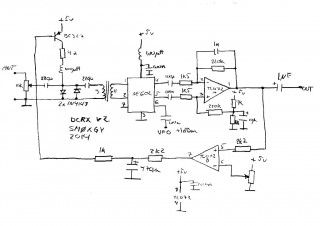
This is a junk-box build so component values are not optimal. Looking at the signal path from left to right there is a variable attenuator at first using a simple potentiometer. After that there are two protection diodes. One of which is also used for the variable attenuator. I did not have any PIN diodes at home but regular 1N4148 worked well. Next is a matching transformer. The input impedance of the NE612 is 1500kOhm according to the datasheet. I had no spare toroids at home so the core of the transformer is actually an RFI choke from an old VGA cable.
Remember: N1/N2=sqrt(Z1/Z2)
The output from the mixer in a direct conversion receiver is low level AF and is prone to pick up noise. One really good thing about the NE612 is that it is balanced. I kept the balanced signal for the first op-amp AF amplifier. That improves the signal to noise ratio quite a bit. The first AF amplifier also serves as a low pass filter. The AF output is then routed back to the second half of the op-amp that is working as a comparator. The purpose of this comparator is to detect high level signals and adjust the variable attenuator at the RF input. This makes up a crude "AGC" like function. The aggressiveness of the automatic attenuator is set using the comparator reference potentiometer.
External LO from my signal generator is fed to the NE612 through a decoupling capacitor. Signal level is fixed at +1dBm. Going any higher does not improve signal receive quality and may damage the NE612.
Also note that no BPF is used on the RF input. I initially planned to make this a single band 40M receiver but after some experimenting I realized that this design would work well for a general coverage receiver. If strong broadcast transmitters are close I suspect there would be trouble but that is not an issue at my location.
The output AF signal also drives the simple power amplifier seen below. Some additional low pass filtering is added here as well.
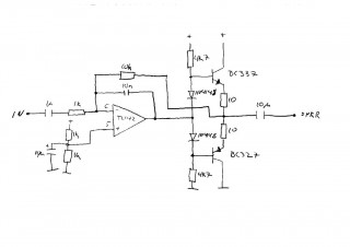
I know the amplifier could be a lot better but I found the amplified signal from this circuit to be more pleasing to the ear than the signal from an LM386.
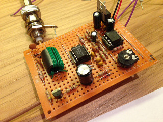
Below is the final receiver. Power amplifier is not included on this board. Note that the potentiometer on the RF input is not mounted. I did not need it after implementing the variable attenuator. At least not using my relatively simple antenna (tuned 15m wire). Also present on the board is a 7805 regulator that is not included in the schematic. Having a clean power supply is really important.
After using the receiver for a few weeks I must say that I'm quite pleased and surprised. This thing actually works. And it works quite well. Most signals I can hear just as good on my Icom IC-735 as on this simple receiver. Of course the fact that both sidebands are always received reduces the selectivity of the direct conversion receiver but in case of both sidebands being present in the received signal it may also work in its favor.
To sum it up. A fun and useful project. Now I just have to add a simple DDS VFO for a general coverage HF receiver.
by Butch Lacadie 2014-10-06 15:54 UTC
Dan,
I like your work here. I made a general coverage AM receiver using the NE602 and overloading is a huge issue. For SB/CW I use a simple BFO, same circuit as the ten-tec one. I may try to implement your design in a new receiver.
I also want to try a dual gate mixer like the one used in a Heathkit SW-717. I'm love making SW receivers. The one above uses an arduino/DDS VFO arrangement (youtube it).
by Daniel 2014-12-14 12:07 UTC
I'm glad you like it! Hope it gave you some new ideas and that you have fun experimenting :)
by Alejandro Weber 2015-04-18 23:10 UTC
Hi! Great circuit and explanation. I will make the same circuit for mi DDS VFO with AD9850, my question is how do you estimate the AL value of the ferrite core... I have some toroids but different from this...there is a table or online calculator? Thanks!
Greeting from Argentina
by Daniel 2015-04-20 06:08 UTC
Hi Alejandro! Thank you for reading. Approximating a decent AL value can be tricky. There is no simple formula that I know of. One way is to wind a known number of turns on a toroid and measure the inductance using an LCR-meter. However multiple measurements and a very good (expensive) meter may be required to acquire a usable value.
For impedance matching (as in my circuit above) you usually do not need to know the AL value since the formula can be minimized down to N1/N2=sqrt(Z1/Z2). Where N1 and N2 are the number of turns on the transformer sides and Z1 and Z2 are the impedances on the respective sides. N1 corresponds to Z1 and N2 corresponds to Z2. Some experimentation may be needed to find the optimum number if turns for a specific N1/N2 ratio but on HF this is usually non-critical. You can get away with a lot on HF :) Good luck with your project!
by Jeff Weinmann 2015-08-08 14:29 UTC
Hello Daniel again,
Do you happen to have any youtube videos to demonstrate the audio coming out of this reciever?
Thanks,
Jeff
by Daniel 2015-08-29 11:15 UTC
Hi Jeff! Sorry, no youtube video for this one I'm afraid but thank you for the input. I will keep that in mind for the future :)
by Butch Lacadie 2015-11-18 00:34 UTC
Hello again,
I optimized your AGC for use in a superhet I'm making. I decided on the NE602 which as everyone knows suffers from overload. I spent weeks on a circuit which is now working really good. Thanks so much for coming up with this circuit!
by Daniel 2016-02-08 14:44 UTC
Great work Butch! I'm really glad you found a use for my circuit. It's simple but effective. I'm surprised how well it turned out. It really gives a new life to the NE602 as a front end.
by francesco 2016-04-07 13:13 UTC
Hi.
The pin 7 of NE612 is not connecter, or connected to ground?
many tnx
73
by Daniel 2016-04-30 06:48 UTC
Hi Francesco! Thank you for reading. Pins 6 and 7 can be used for creating a crystal oscillator or feeding a balanced signal. If you provide a single ended signal (as in my circuit above) you can simply just use one of the pins and leave the other one floating/unconnected. I realize that I should have written "NC" on pin 7 in my schematic for clarity. Oh well :) 73 de SM0XGY
by Trent 2016-05-05 20:59 UTC
Hi,The transformer you made how well does it work because for 50-1.5K there isnt enough turns and also have you every tryed a RF preamp on the input
by Jon 2016-12-01 17:17 UTC
Thanks for the article, it has inspired me to try a direct conversion receiver.
You seem to have an extra diode next to the 220R (which I think is 2k2 on the schematic) resistor on your prototype, but not on the schematic.
Is this to modify the response of the AGC, ie a quicker cap discharge? Or is it for something else?
by Daniel 2016-12-01 20:47 UTC
That you for noticing Jon! You are absolutely right on every point. Very sorry about the confusion. I was experimenting with a lot of values and combinations. Can't believe I missed it. That 2k2 ohm resistor is really 220 ohm in parallel with a 1N4148 diode. The diode made a minor but definitely noticeable difference.
by Andy 2017-10-09 10:13 UTC
Hi Daniel. A friend directed me to this page after I described my own NE612/TL082 design to him. Mine is very close to yours, except that I have used DC coupling all the way from the mixer o/p to the output. Obviously when using a DC RX on an AM signal, there is a heterodyne which reaches 'zero beat' when the LO is bang on. At a fraction of a Hz detuning, the DC level gently wafts up & down at a rate determined by the tuning error. I can't help wondering if this could be used for something. I like your AGC system and may try it myself. These simple RX's are fascinating and fun, even though I have some very posh receivers in my shack! Good luck.
by Jason 2019-03-11 00:00 UTC
Thank you for this awesome project. Building this kept me occupied during a recent snow storm. The receive on this is very nice. I put it into a nice clear package and I plan on using it often and to showcase it at my school to hopefully get some kids interested.
73
KB2SDR
by Electrojim 2019-04-01 19:14 UTC
A most inspiring write-up, Daniel! I'm intrigued by your AGC, wondering whether a forward-biased diode might make the receiver more susceptible to intermod. From what I've read, PIN diodes are better for this, and did read somewhere that a rectifier diode, like a 1N4001, acts much like a PIN diode in applications such as this. I am designing a receiver at present that will use the SA602 as a first, up-conversion mixer, and a second one to bring the IF down to about 300kHz. In my application up-conversion makes a preselector unnecessary unless the 602 is indeed susceptible to input overload. Time will tell. Thanks so much for the write-up and opportunity to chime-in.
by PRAVEEN 2020-09-14 18:16 UTC
Thanks a lot Daniel.. Building this was a fun.. I found adding a 1uf capacitor between Pin 5&7 of AGC comparator (Converting Comparator to Integrator) will give stable performance. Currently it is just a comparator. If the circuit is fed with strong RF signal, Input attenuator may switch fastly between ATTENUATE and RELEASE modes which can damage Audio..
73
VU3UJW
by Ken W1HV 2021-03-08 01:15 UTC
Good evening Daniel - I much enjoyed your article on the NE602 /SA612 receiver. I am building the circuit with slightly improved & quieter ICs for the audio sections. Question do you have an updated schematic with all the improvements? Do you have a dual conversion circuit in the works as well? Much appreciated. Do you have an email to share?
73, Ken
by Ken 2023-02-22 02:09 UTC
Hi Daniel
I know this posting is very old, but I am curious about something. In your article above you said
"External LO from my signal generator is fed to the NE612 through a decoupling capacitor. Signal level is fixed at +1dBm. Going any higher does not improve signal receive quality and may damage the NE612."
Do you recall if you used a sine wave signal generator or square wave ?
73 Ken
by david 2023-03-05 19:44 UTC
May I know how to calculate the turn ratio and how to build the transformer? is that for double balanced input right? thank you
Write a comment