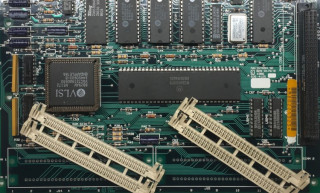
For many years I have had an old Macintosh SE logic board that was scrapped out from an old Apple repair shop. Someone had broken the SIMM sockets at some point by snapping the retaining clips at the ends. A common problem unfortunately. I guess the repair shop didn't want to bother and just put it aside. When they eventually went out of business the board ended up in my hands. Besides the broken sockets it was in good condition and most importantly, no leaky battery damage.
I have found no reliable way to repair SIMM sockets with snapped clips so I figured the best way would be to replace them. Some care must be taken while desoldering as usual but with patience and proper tools it's pretty straight forward. Apple used one pair of dual sockets meaning there are 60 pins to desolder for each.
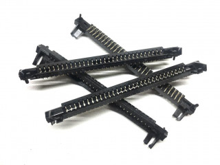
I did not have the exact same dual socket replacements but I did have single sockets. They are not as robust as their dual socket counterparts but since this Macintish SE board will be fully populated with its 4x1MB memory anyway I don't expect to replace the memory sticks very often, if ever.
Now with the memory socket problem out of the way it was time for the next challenge.
How to test a compact Mac logic board with out the rest of the machine
I have a few compact Macs including the Mac SE so I could potentially swap the boards around and test this out but I didn't want to disturb them and risk causing problems on working machines so I started playing with the idea of finding a way to use these boards without the matching CRT, analog board and power supply. This is something that I have wanted to try for a long time.
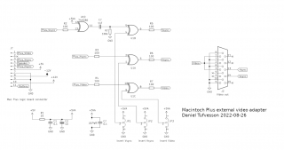
The compact Mac SE design uses a single connector on the logic board for power supply and video output. This is the same type of Molex Micro-Fit connector commonly used today in modern PC power supplies but in the 2x7 pin configuration. I dug out the smallest spare ATX power supply I had and a new 2x7 Micro-Fit plug. I extracted the crimp terminals from the ATX 10x2 pin motherboard connector housing and re-arranged them into the 2x7 pin housing to match the Mac SE logic board connector. See the pinout in the schematic below. I removed all unneeded cables from the ATX power supply and hot-wired the power-on signal so that I could power on/off using the mains switch.
The Macintosh SE logic board connector supply rails are +5V, -5V, +12V, -12V but the -5V is not used by the board itself and just routed through to the expansion slot. +12V and -12V are used for the serial port level drivers and audio amplifier. +12V is needed for the floppy drives.
The connector also provides the video output divided into three different signals; vertical sync, horizontal sync and video pixel data.
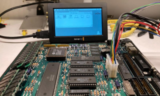
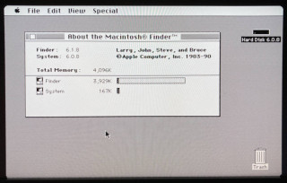
After double-checking and triple-checking and checking it all again a few times I powered up the board with meters on all supply rails and scope on the video/sync pins. All voltages looked good and I was happy to see a valid video signal being generated!
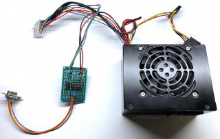
Above is a picture of the power supply and wire harness along with the video adapter board I ended up building.
The video output is at TTL level. The horizontal and vertical sync signals are active low and the video is inverted (low=white and high=black). The vertical frequency is a reasonable 60.15Hz but the horizontal frequency is a little unusual at 22.25kHz. I would place it somewhere between CGA and VGA. The horizontal signal is also unusually long and extends well into the visible area of the video lines. Not knowing exactly how to process this video I built a small adapter board containing an XOR gate for buffering as well as the possibility to invert all signals. The board also includes serial resistors for protection (don't want to accidentally fry any of the video output pins on the logic board!). For the final output I decided to use a standard 15 pin VGA connector with the R, G and B signals bridged to provide a B/W image. I figured it was the closest match and will make it easy to test on multi-sync monitors as well as one of the Swiss army knives of video, the
Open Source Scan Converter.
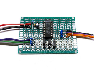
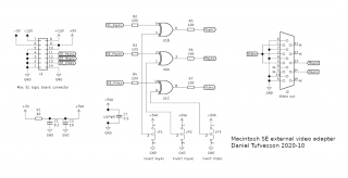
Here is a schematic over the completed video adapter based on the 74HCT86 XOR gate. I added some extra filtering on the supply as well as jumpers for selecting whether any of the signals should be inverted or not. The series resistors on the input is for protecting the outputs of the logic board and to reduce ringing on the signals. Same goes for the output side but here the series resistor of the video output is also needed to reduce the level a little bit closer to the VGA standard. Bridging the 75 Ohm R, G and B inputs of the VGA connector will present a 25 Ohm load and this in series with a 100 Ohm resistor will convert the 0-5V from the buffer down to 0-1V more suitable for a VGA input. In reality it should be 0-0.7V but it's close enough for B/W video (I don't expect the gate to reach full rail voltage either). The resistors on the TTL sync outputs will not affect the levels much but will provide some additional protection.
Results
Not expecting any miracles, I started by connecting the board directly to my Dell U2410 monitor.
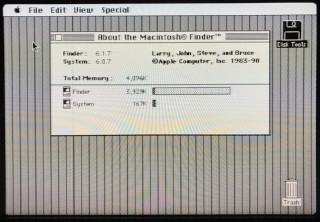
As expected the result was underwhelming but at least the monitor did sync on the signal. The resolution and scaling was incorrectly detected which caused the vertical lines.
Next I tried using the
Open Source Scan Converter which did a much better job of dealing with the non-standard signal. If you do not know what the OSSC is then check it out
here. It's basically a device that scales an analog video signal into a reasonably valid HDMI or DVI signal. Just what we need here.
Using the OSSC the results was much better! The auto-detect did not detect the signal properly and needed a little help but after a little tweaking the picture was perfect. These are the OSSC parameters I used:
- Horizontal sample rate = 704.00
- Horizontal sync length = 14
- Horizontal back porch = 164
- Horizontal active pixels = 512
- Vertical sync length = 1
- Vertical back porch = 26
- Vertical active pixels = 342
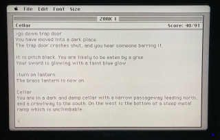
Another photo of the screen with OSSC scan lines added. Almost like sitting in front of a real compact Mac. A modern monitor with 16:10 aspect ratio is not too bad for this purpose actually since it is not that far from the aspect ratio of the compact Mac.
2022-08-28: Update for the Macintosh Plus
When trying the same thing on a Macintosh Plus I could not get any monitor or the OSSC to sync on the output. On paper the specifications for the video on the Mac Plus is the same as for the Mac SE above so in theory it should have worked. This had me stumped for a while until I had a look at the vertical sync. The start of the Mac Plus vertical sync signal aligns with the Mac SE but it is ridiculously long. Over 20 lines! For comparison regular VGA, and the Mac SE, has a vertical sync signal that is around 4 lines long. I made another adapter specifically for the Mac Plus that incorporated an extra circuit to shorten the vertical sync signal. There was a free '86 gate available so I just used that as an inverter and then a simple RC filter. It worked really well and the OSSC can now lock onto the Mac Plus video signal without any issues.