I²C is a fun protocol. It's great for interfacing to real time clocks, sensors, displays etc. My personal favorite right now is the Si5351 frequency generator chip. In a world of ever increasing number of I²C compatible micro-controllers, I though that my MC3 should learn to speak I²C as well. I have chosen a chip from Philips that is a self-contained I²C interface. It's much faster than bit-banging an I/O port. The chip,
PCF8584, can still be obtained from various suppliers but I don't think it's being manufactured anymore. Therefore I have taken extra care to protect it. The interface schematic can be seen below.
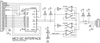
The tricky part about buffering I²C signals is that they are bi-directional. A buffer that is both bi-directional and has open collector input/outputs needs some extra thinking. It is not possible to just put to buffers back to back and expect it to work. As soon as one of the buffers trigger the opposite buffer will also trigger and the circuit will enter a locked state. To solve this I have designed the buffer stages using two comparators (LM339) with open collector outputs. By using comparators it is possible to carefully adjust the trigger levels so that one buffer does not affect the buffer in opposite direction. A reference voltage of 0.65V is used for the comparators, but the output from the comparators facing the PCF8584 has a series resistor that together with the pull-up resistor creates a voltage divider. When the comparator tries to pull the line low the divider will limit the voltage to around 1.2V, enough for the PCF8584 to register a 'low' level but not enough to trigger the opposite comparator.
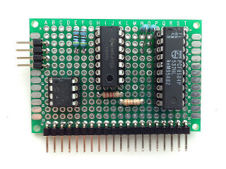
This is the finished MC3 I/O board. I added an 8-pin socket (not in the schematic) for connecting EEPROMs directly on the board. As always, don't forget to add 100nF decoupling capacitors across the supply on all chips.
Sample program for testing the interface
This program interfaces to a DS1307 RTC chip but I have made the I²C driver routines generic so they can be used for accessing any other I²C device as well.
-
source
-
listing
-
s19