Yet again I feel like way to much time has passed since my latest project update. Or any update at all for that matter. This time I'm revisiting the world of early computing mass storage, namely,
audio cassettes.
Background
Many of you probably have this love-hate relationship to data on audio cassettes. You know how unreliable and tediously slow it is but at the same time it has this cozy aura around it. I will never forget those times waiting half an hour for the program to load only to realize there was a load error and you had to do it all over again. Not to mention winding the tape back and forth according tho those hand written scrabbles and notes of various tape position values to find your precious data. Very hands on in a way modern computing rarely is today. I felt that my MC3 computer was missing out on a lot of fun so I decided to make an audio cassette interface for it.
Tapes and recorders
Data on audio tapes is nothing more than tones that the computer can generate and interpret when played back. The audio must be constrained to the limitations of the audio cassette and the recorder used. There are many variants here but I will focus on the, probably most common,
Compact Audio Cassette format.

There are different types of magnetic tapes in those cassettes that yields different frequency responses. Generally you have a usable response up to around 15kHz using a "normal" iron oxide tape. Chrome or metal tapes can have a frequency response of up to 20kHz when using good tapes and good recorder. Also cassettes made for shorter recording times are usually made out of thicker material thus making them more robust and perform slightly better. My goal is to store data using
normal tapes together with a
Panasonic RQ-2102 recorder. The RQ-2102 is a quite common recorder that has been in production for a long time and has historically been popular among computer users. It was even the recommended recorder by Woz himself for use together with the Apple I.
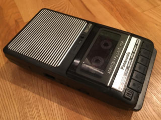
I think I have the latest incarnation of the RQ-2102. It has changed appearance slightly during the years but the function and performance has been more or less the same as far as I know. Unfortunately the RQ-2102 is not equipped with a remote jack for controlling the motor from the computer which would be a nice feature to have but for my purposes it will do just fine.
Hardware
This is actually a very simple I/O card for my MC3 computer. There is a trade-off to be made here between hardware complexity, performance and flexibility. A complex interface that do most of the encoding and decoding in hardware will perform good but is most likely not very flexible. A simple interface, like the one I have here, do the encoding and decoding in software and because of that it is flexible and could, in theory, handle different encodings by using different software algorithms. Most home computers from the cassette era used simple bit-banged interfaces, just like this one, and software based encodings. That made it possible for users to develop custom loaders for example and exchange cassettes between different systems.
My cassette interface is no more than a software controlled single bit I/O port and single bit ADC/DAC and the whole circuit fit on a small MC3 I/O board.
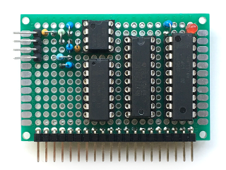
The digital part of this board is not very exciting. It's just a '244 buffer (U3) for reading and a '374 latch (U4) for writing. That makes up 7 more bits than actually needed but they may come of use some day, who knows.
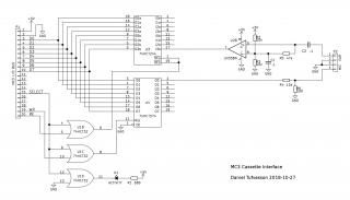
By writing and toggling bit zero, an audio square wave can be generated and recorded on to the tape. A simple resistor divider brings the output level from the '374 down to microphone level for the tape recorder's input. Some experimenting may be required here to find a good level but in the schematic are the values that I found worked well for my RQ-2102.
Reading back the waveform reliably from the recorder is a little bit more complicated. There is no guarantee that the shape and amplitude of the waveform is maintained during recording and playback. Therefore a bit of analog trickery is needed here to shape the incoming signal back into a logic level square wave that can be sampled by the '244 buffer input. I do this by using an LM358 op-amp (U2) connected as a comparator. The incoming signal is passed through a capacitor and biased at Vcc/2. The negative input of the op-amp is fixed at the same Vcc/2 and the positive input is fed the biased input from the recorder. This way, zero-crossings in the incoming signal are detected and converted to a logic level square wave that the '244 can pick up reliably.
Because of the bit-banging and timing critical nature of this interface I also added an LED to show activity on the board since the CPU will most likely be too busy to write anything useful to the console during operation. An LED is a crude way to at least give some clue about what is going on.
Initial testing
First off let me just explain why I choose to use bit zero for the output and bit seven for the input. The reasons for this is on the software side. Access to the interface must be made fast and efficient. Using bit zero for the output makes sense since bit zero of a register can quickly be toggled using a DEC or INC instruction. Similarly using bit seven for the input means that conditional branches can be made based on the bit value by using BMI and BPL instructions. These two tricks may seem insignificant but it can be a big advantage when timing is critical.
To verify that the interface was in fact working I made a simple loop to mirror the input to the output.
casport equ     $8060
        org     $0100
loop    ldaa    casport
        rola
        rola
        staa    casport
        bra     loop
Bit seven is read and shifted around to bit zero and written back in an endless loop. By using a signal generator and oscilloscope I was able to verify that the circuit was working as intended.
Storing bits
With the knowledge that the hardware side of the project was working I began tinkering with a simple low level format for data on tapes. Instead of trying to develop software to support an existing format I decided to start from scratch and make something of my own to cover the basics and to verify the concept.
It's important to keep the signal moving in order to lock on to the data stream. Never let it be static for too long. I decided to go for an encoding scheme that uses one cycle per bit. There are many ways to accomplish this but I ended up implementing these three variants.
1. Frequency shifting
One cycle of a high frequency represents "0" and a single cycle of low frequency represents "1". This effectively makes ones and zeros have different length. That means the average bit rate will vary depending on the distribution of ones and zeros.
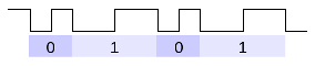
2. Varying pulse lengths
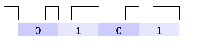
Here the cycles has been evened out to be the same length. The short cycle has been made longer and the longer cycle has been made shorter. The relationship between the high part and the low part of the cycle determines if represents "1" or "0". This makes the bit rate constant regardless of the content.
3. Combination of
1 and
2
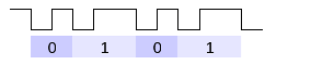
In this case only the length of one half of the cycle determines the bit content. The average bit rate should be the highest of the three but still vary with the content, albeit to a lesser extent.
With some clever coding I hope to support all three variants in the same loading routine.
Structure
In order to load data back from tape we need a way to locate the first bit of the first byte of the data stream. The software would need a specific synchronization pattern to look for. I decided to make it simple and use a synchronization pattern consisting of a relatively long sequence of consecutive ones followed by a single zero to indicate end of sync.
Data is then followed directly after the sync. I decided to have one start bit for each byte and then the bytes are clocked out with the least significant bit first. The start bit has the value zero since the sync pattern is made up from ones. That way it's possible to indicate end of data by sending another sync pattern of ones. The start bit also gives some small level of phase error checking. A better way may be to also add a parity bit to every byte but I will leave that for another time.
This is the final structure I ended up with:
1. Synchronization pattern consisting of 2048 bits "1" and one single bit "0"
2. Start bit "0"
3. Eight data bits, LSB first
4. Repeat 2 & 3 until end of data
5. Synchronization pattern again
By ending with an identical synchronization pattern as the one in the beginning it's possible to add several consecutive data segments but for now I will start with only one to keep it simple.
Software implementation of SAVE routine
The save routine is pretty strait forward. I created separate bit delay subroutines to make it possible to easily change the bit rate. There is a subroutine for generating the sync pattern and a subroutine for sending a single byte. Saving data is done in a simple loop until all bytes are saved. The routine implements variant number
three (see above) where the length of the high portion of the cycle determines the bit value. I set the timing in a way that makes the a "1" bit have twice the length as a "0" bit.
The save routine asks for a start address and an end address to select what data is to be stored on tape.
Below is an example printout when running the program. User input in blue text.
> j a100
BegAddr: 1000
EndAddr: 14ff
Start tape and press enter <CR>
OK

>
This is what it sounds like:
audio clip (watch your playback volume!)
Average data rate is around 255-300bps using this program. This could be improved with other timing parameters.
Download my experimental tape save routine:
-
source
-
listing
-
s19
Software implementation of LOAD routine
The load routine is a little more complicated. Care must be taken here to accommodate different timings and possibly different tape speeds and bit rates. My goal was to make it robust enough to automatically detect the bit rate and load data without requiring the user to set any additional parameters. The bit rate is determined by averaging the cycle time of the synchronization pattern.
The core part of the load routine is this subroutine, "cycle", that measures the time of the high portion of a cycle.
cycle:	clra
	ldab	casport
	bmi	cycle3		; if high on entry we are out of sync
cycle0:	inca
	beq	cycle3		; timeout
	ldab	casport
	bpl	cycle0		; wait for positive flank
	clra
cycle1:	inca
	beq	cycle3		; timeout
	ldab	casport
	bmi	cycle1		; wait for negative flank
cycle3:	rts
The routine will return the time in A. When A is zero it indicates a timeout or that the routine was entered during a high portion of a cycle. This is used for error detection and to initially find and lock on to the synchronization pattern.
The program begins by asking where in memory to store the data from the tape.
When loading starts the program calls "cycle" repeatedly until a steady stream of cycles are found. That is detected when "cycle" returns a non zero value on every call. The first 256 steady cycles are used to determine the cycle time using a running average.
Knowing the cycle time for the sync portion means we know the cycle time for a "1" bit and from that a threshold value is calculated that sits between a "1" cycle time and a "0" cycle time.
Cycle time threshold value is the calculated using the formula:
threshold = cycletime - cycletime/4. This is based on the assumption that the length of a "1" bit is twice the length of a "0" bit, thus this calculation places the threshold value right in between those values.
After the cycle time has been calculated the program monitors the stream to make sure there is no interruption. If the bit stream is interrupted the synchronization will restart from the beginning again. As soon as a cycle time corresponding to a "0" bit is found it marks the end of the synchronization and data will follow.
Data loading checks for a "0" start bit and receives eight bits and stores to memory. This is repeated until the start bit is not "0". This indicates either an error situation or that the ending synchronization has started.
Below is an example printout when running the program. User input in blue text.
> j a100
DstAddr: 1000
Press enter and start tape <CR>
Stop at 14FF

>
Download my experimental tape load routine:
-
source
-
listing
-
s19
Implementation for MCFS2
Of course I couldn't resist making a few tools for my MCFS2 system as well. I created a simple checksum calculator also as a way to verify the tapes after load.
casisave.asm - Cassette interface save (file to tape)
- Syntax: casisave <filename>
casiload.asm - Cassette interface load (tape to file)
- Syntax: casiload <filename>
chksum.asm - 16bit checksum calculator
- Syntax: chksum <filename>
Summary
These programs provide a relatively crude way of storing data on tapes but I think it's a good proof of concept. More work is needed to develop a proper format and error handling to make this usable in a real world scenario. Perhaps even a header with file meta data. That would be nice. This has been a fun project. It reminded me of time spent with the KIM-1 all those years ago. The reliability surprises me actually. No failed loads at all so far.