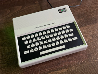
Shortly after I started my MC3 computer project I became aware of another computer from back in the day that was eerily similar in name and CPU choice. The TRS-80 MC-10 by RadioShack. From what I understand it was marketed as a low cost alternative to the bigger TRS-80 Color Computer but it did not sell very well. Here in Sweden it is very rare.
Basic specs
- Processor: MC6803 0.89 MHz (derived from the 3.579545 MHz NTSC color crystal)
- Video generator: MC6847 (only RF output)
- Sound output: Single bit software flip-flop
- RAM: 4kB
- ROM: 8kB
- Storage: Cassette I/O
- Expansion: Bit banged RS232 and an expansion port with access to system bus
- Keyboard: 48-keys "Chiclet" that is actually not that bad
My MC-10 is originally from Canada so it's an NTSC version. I've heard rumors of a PAL version but never seen one. First I tried hooking it up to my modern LCD TV but it did not work very well. The MC-10 can be set to either CH3 och CH4. Not only was the image practically unusable but CH3 did not work at all and setting it to CH4 made it sort of work if I the TV was set to CH3. The RF-modulator was clearly out of tune.
This is the best image I managed to get out of my Samsung TV. Not good enough. Let's pop the hood and see what can be done!
Armed with the
service manual and
schematic I went in.
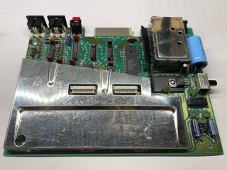
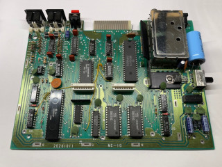
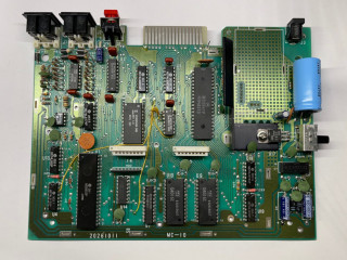
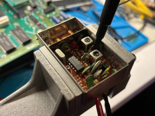
RadioShack sure tried to meet regulations with the MC-10. That shield is thick and needed a lot of heat to desolder. There is a shield on the back of the PCB as well held on by small clamps.
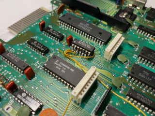
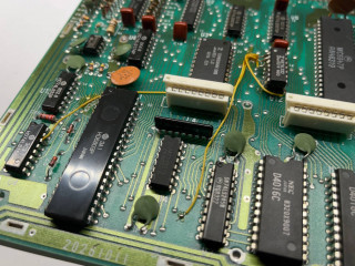
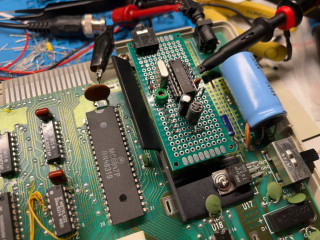
That bodgy looking 74LS32 is actually part of the official schematic. It even has a label. It’s a fix for making the code in ROM detect the correct amount of RAM (more on this later).
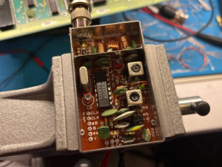
Let’s get that RF modulator out of there and have a closer look. No surprises on the PCB under the RF-modulator. The machine gets its main clock from the RF-modulator though so it will not work without it and the chip inside (MC1372) is actually the NTSC color encoder so the RF-modulator is an important part of the machine.
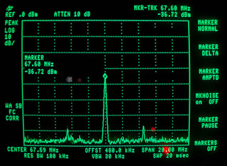
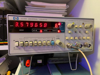
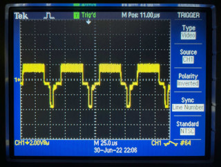
A quick look on the spectrum analyzer made it clear why I could not get my TV to lock on the MC-10 signal. Here the modulator is set to CH3 (61.25MHz) but the actual carrier at 67.60Mhz is closer to CH4 (67.65MHz). The audio sub carrier side bands are clearly visible though.
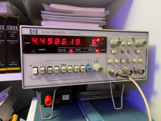
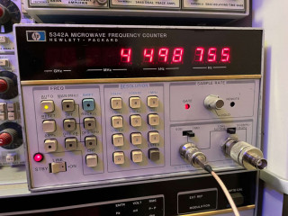
The MC-10 RF modulator 4.5MHz audio sub carrier is there and looks to be reasonably within specs. The HP 5316A and the HP 5342A are both on the same frequency reference and displays a little differently. Most likely due to the different load they put on the oscillator.
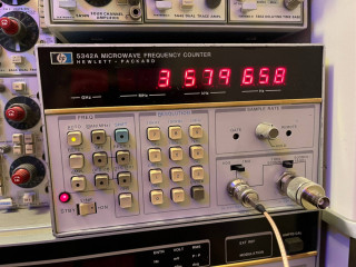
The color crystal oscillator should be 3.579545MHz and is easier to measure reliably. Needs a little tweaking but is not the reason the MC-10 RF modulator carrier is off frequency.
I decided not to dive deeper into this and instead focus on how to get a composite video signal out of this machine.
Even though the MC1372 is designed to generate an RF signal, there is a paragraph in the datasheet about striping the RF oscillator from the circuit and having it generate composite video.
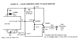
I pulled the crystal and the MC1372 from the original modulator and put them on a breadboard roughly the size of the original modulator.
Followed the examples straight from the MC6847 and MC1372 datasheets and got something that sure looks like a composite video signal!
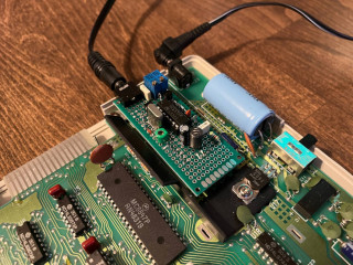
Moved on by adding the final two transistor output stage as described in the datasheet as well as two trimmers to set the working point of the amplifier. After some quick adjustment I was greeted with a very nice and colorful image. The output is a 3.5mm stereo jack placed in the same spot as the original RCA RF output on the modulator. This way I have both video and audio output without any modification to the case. Added an attenuator and low-pass filter for the single flippy bit audio and routed it to the jack as well. Now I could finally use the TRS-80 MC-10!
Poking around
Now when I could actually look at the video output without imminent headache I started looking around using the built-in basic and the original manual. Turns out that the keyboard is actually not that bad for something like this. The thing that takes some getting used to is that there is no backspace key. To correct your typing errors you either have to press CTRL+A which will act at backspace, or CTRL+Q which will delete the entire line. There is also only one SHIFT key, to the right, and only one CONTROL key, to the left. This takes some getting used to but after a while the typing experience is actually quite good.
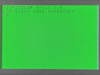
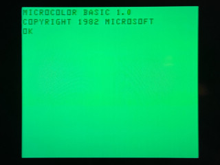
On power on you are greeted with the basic startup screen.
MICROCOLOR BASIC 1.0
COPYRIGHT 1982 MICROSOFT
That is very similar as the original 6803 Microsoft basic.
MICROSOFT BASIC VER. 1.0
COPYRIGHT 1982 MICROSOFT
Comparing the disassembled MC-10 ROM with the Microsoft 6803 basic source reveals that, indeed, it is the Microsoft basic with a few added custom tokens like SOUND for making noise and SET, RESET and POINT for modifying video memory etc. In general the basic is a very run of the mill Microsoft basic which is a good thing.
Memory map
Digging further into the address decoding reveals some of the, lets call them cost saving, choices made by RadioShack. The 4k of RAM is located at all the way up at $4000-$4FFF and the incomplete address decoding makes the RAM also appear at $6000-$6FFF.
The schematic explains a bit of this. The 64k address space is divided into four 16k chunks by the U4 74LS155 decoder.
The first 16k chunk is unconnected making the only thing existing there is the internal CPU registers and devices.
The second 16k chunk is the RAM of which only 4k is used. That's the reason for the RAM showing up at two locations, and also the reason for the bodged in U20 74LS32 which is used to disable write to RAM in the second 4k area just beyond end of real RAM. I suspect this is to make the Basic detect the correct amount of RAM on startup. The Basic memory size detection routine is quite crude and will continue counting mirrored RAM as new RAM as long as it is writable. Here RadioShack simply opted for a hardware patch instead of altering the ROM.
The third 16k chunk is decoded into two single byte devices, one latch on write (U8) which controls the five bit VDP config register and one bit sound output, and one buffer on read (U14) which scans the keyboard.
The last 16k area is used for the ROM. Here RadioShack made it possible to use both 8k and 16k ROMs but only 8k was ever used as far as I know. This means, just like the RAM, the ROM is mirrored on this area. One thing to watch out for here is that the ROM is referenced to using the lower half of the 16k area but the CPU vectors are at the top of the 16k area which relies on the ROM being mirrored.
To sum it up the memory map looks like this:
$0000-$001F --- 6803 internal registers
$0020-$007F --- UNUSED
$0080-$00FF --- 6803 internal RAM
$0100-$3FFF --- UNUSED
$4000-$4FFF --- 4kB RAM
$5000-$5FFF --- mirror of 4kB RAM (read only)
$6000-$6FFF --- mirror of 4kB RAM (writable)
$7000-$7FFF --- mirror of 4kB RAM (read only)
$8000-$BFFF --- Minimally decoded single byte I/O slot for keyboard, VDG control and sound out
$C000-$FFFF --- 16kB ROM but only 8kB used and mirrored twice
I will continue exploring the MC-10. One of the first things I will start working on is some form of memory expansion. 4k is simply too little to make use of all the things this machine is capable of.