Video generation in computing has historically been a somewhat tricky business. Nowadays in modern high-speed systems it's not really an issue but 30 years ago things were different. A video display must generally be constantly refreshed and fed with an uninterrupted stream of data and synchronization pulses in order to display a stable picture. The data is normally read from a dedicated video memory, over and over again for each screen refresh. The CPU needs to access this memory in between the reads in order to update the picture on the display. This is a timing accident bound to happen. Especially if the system bus needs to run at a completely different clock than the video display. Perhaps even totally asynchronous to each other. The most common technique used in the past is to simply avoid the issue by running the CPU and the video display at the same clock. Not just the same rate but exactly the same clock. That way the CPU and video interface can take turns accessing the common video memory. This is a simple and effective method but has its limitations in speed and flexibility. I wanted to build a video interface for my MC3 6303 computer that could handle an asynchronous bus clock without getting overly complicated. This is an idea that has been lurking in the back of my head for several years but I've never really taken the time to realize it. Until now.
The video interface I'm presenting here is made to be simple and understandable while using all discreet logic. I've seen many "retro" video projects today that uses a modern microcontroller to generate video. That just doesn't feel right. Almost on the brink of cheating.
Specifications
- Standard B/W PAL composite video output
- Fully bitmapped 16kB memory
- Around 400x256 pixels usable resolution depending on the TV/monitor in use
- Built using commonly available IC's
Circuit description
This is a bitmapped interface meaning it has no character generator, sprites, hardware scrolling or any other fancy stuff. The bits in memory are displayed on screen. That's it. Character generator and hardware scrolling would be relatively simple to implement but I've left that out for now.
The main concept is that the whole interface is driven by a constantly running 18bit binary ripple counter built around two 4040 cascaded counters clocked at 8MHz. All timing is derived from this counter and the same counter is also used for iterating through the video RAM. PAL video lines are 64us long. With a pixel clock of 8MHz there is room for roughly 512 pixels on each line (some of which are hidden under the horizontal sync signal and some who is outside the safe video area). This means that the lower 9bits of the counter are counting pixels on each video line and the upper 9bits are counting video lines on each frame. PAL uses 625 interlaced lines. Interlacing is of no use here so I opted for progressive video with half the resolution which is roughly 312 lines. The video synchronization pulses are generated from the counter outputs using logic gates. A composite sync is generated by a simple XOR of both HSYNC and VSYNC.
All gates are 74HCT regardless of what the schematics says.
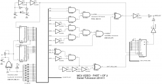
Above is the first part of the schematic for the video interface showing the counters and gates that generates the video synchronization signals. In order to maintain a 50Hz refresh rate the counter needs to be reset after 312 lines. The reset is performed using a diode network that triggers the reset signal at 512 pixels * 312 lines = 159744. Actually I chose the value 159743 as reset value (one pixel early). The precise reset timing can then be set by adjusting R6. If the reset is just a tiny bit off then the image will be skewed at the top and that's not pretty at all.
Also visible in the schematic is the shift register for shifting out the individual video pixels. Every eighth pixel the shift register is loaded with a new value, thus every line covers 64 Bytes of data. The second part of the schematic just have to make sure the correct data is available for the shift register at this time.
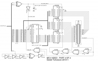
Above is the second part of the schematic. This part shows the bus interface and the video memory (Cypress CY7C199-20PC). The bus interface consists of three latches. These latches triggers on writes to MC3 I/O-page 4 (16kB) and holds the address and data values until the video interface is ready to receive it. My MC3 computer has regular memory in this area so this design is actually mirroring a CPU accessible memory area to a local memory area on the video interface making the video RAM, from a software point of view, behave as regular RAM that can be both read and written to.
Two timing signals are generated to accomplish this. One signal (generated by IC7A and C1) that alternates the RAM direction from either writing data from the latches or reading data to the shift register. This means that in a cycle of eight pixels the RAM is read once and written once. The second signal is the write strobe to the memory. I've chosen a relatively fast 20ns memory for this design, the type of memory that can normally be found in 386/486 PC's as cache memory.
The RAM address bus is directly connected to the latches and connected to the counter via 1k resistors. This avoids the need for additional muxes since the latches can then simply force the address bus to a specific value when writing to RAM, regardless of the current counter value.
The bus latches are read at a rate of 1MHz. As long as writes from the system bus are not too frequent then data will not be missed. My MC3 system bus runs at 1.2288MHz and writes are performed nowhere near every E cycle so there is plenty of time for the video interface to read the data. I think a bus rate of up to perhaps 2-4MHz should be possible using this technique since most CPU's cannot perform writes at every cycle anyway.
 Construction
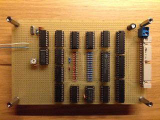
As with the other boards in my MC3 system the video interface is built on a prototyping board using soldered wire-wrap wire. I was a little bit worried about signal quality and noise using this method but I've had no problems so far. The video output is very clean.
Some space left over for eventual additions. The only trimming point is the variable resistor for the counter reset timing. This has not needed any re-adjustments so it appears to be stable.
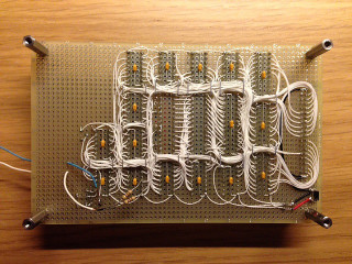
Note the temporary video output connection and the simple two resistor mixer. I have not yet fully decided on the best way to drive the output. Also take note of the decoupling capacitors on all chips. They are not in the schematic but are important.
Results
Below are some sample photos showing what is possible with this interface.
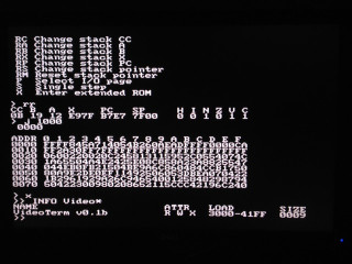
Quick and dirty text terminal showing various commands from my MC3 monitor program. Resolution is 50 columns by 32 rows when using a 8x8 font.
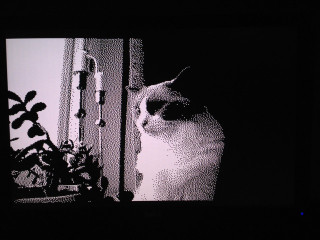
This is a 400x256 photo of the house cat glaring through the window. Using dithering to imitate gray scale.
On 2022-06-04 our beloved cat sadly passed away just one month short of his 10th birthday.
We miss you immensely little angel <3
Known issues and limitations
This interface has been running pretty solid but there are however a few minor issues so far that I have noted.
1. The quick and dirty video output driver stage consisting of two '04 inverters and two 470ohm resistors do not really comply with the broadcast standard but most TVs/monitors have no problem with this. This should be improved upon, thereof the currently temporary video connection and driver. Need to sort this out.
Now fixed. See below.
2. Since the video run completely asynchronous to the CPU, some banding may show for fast repeated fills. By implementing a double-buffered memory synchronized with the vertical sync or writing only when video is not drawing this may be avoided but tearing is only visible under certain extreme conditions so it's not really an issue. I have not seen snowing or any other types of artifacts.
3. Scrolling is slow when used as a text terminal. This is the most significant issue so far. Since this interface has no hardware for scrolling in any direction, scrolling has to be performed by copying large amounts of data in video RAM. This causes a slowdown when the interface is used as a terminal where normally the entire screen is scrolled upwards for every new line. Next step would be to implement scrolling in hardware (basically just a latch and an adder) to achieve vertical scrolling with just a single register write.
Update 2016-08-07 - Better output stage
I have now built a prettier video output driver stage. It can still be improved upon but it's a lot better than the two resistors that were not even close to the correct impedance. Schematic can be seen below.
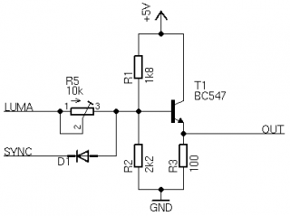
This is basically a simple transistor amplifier and signal mixer with two inputs, LUMA and SYNC, taken from IC7 pin 12 and pin 10 respectively. None of the component values are very critical. R3 should be around 75 ohm but 100 ohm worked just fine for me. The brightness of the output video can be adjusted with R5. This also affects the working point of the amplifier and is one of the reasons that the component values are not really critical. D1 is a general silicon small signal diode. I tested with 1N4148 and BAT42. Both worked fine. The reason for using a diode is to make sure that the SYNC signal always pulls the output low regardless of the LUMA level. This ensures proper synchronization even if erroneous pixels are being clocked out.
A proper output stage was really the only issue left to fix on the video interface. Now this board feels very complete.