Jessie has reached stable and for those of you who don't want to reinstall your system the upgrade procedure is quite straight forward. As always
make sure you have a backup before you start in case something goes wrong.
First step is to make sure you have no special packages installed. Packages from the standard Debian repositories should be safe as well as most of the backports but I strongly recommend to remove packages from third party sources before starting. You also have to be logged in as root to perform the update.
Step 1 - Make sure your Wheezy system is up to date
This is done using the regular apt upgrade procedures.
# apt-get update
# apt-get upgrade
# apt-get dist-upgrade
Also make sure you have the latest keyrings installed.
# apt-get install debian-keyring debian-archive-keyring
Step 2 - Update apt sources and change wheezy to jessie
Edit your
/etc/apt/sources.list and change all 'wheezy' to 'jessie'. Also don't forget to take a look at the files in
/etc/apt/sources.list.d/ (if there are any) and perform the same replace procedure.
Step 3 - Disable X
Since a lot of packages will be updated and daemons will be restarted there is a potential risk of screwing something up when running under X. Go to a regular TTY console and continue the upgrade from there. Alt+F1 or Alt+Ctrl+F1 should get you to the first console. Log in as
root and continue to the next step.
Step 4 - Perform the actual upgrade
When you are logged in to the TTY console. The upgrade process may be initiated.
First we must update the latest sources.
# apt-get clean
# apt-get update
The next two steps is the actual upgrade that will alter the system.
First we perform a normal upgrade. A lot of packages will be replaced and also quite a lot will be kept back. This is normal.
# apt-get upgrade
This is the first step of the actual upgrade. The installer may ask questions that I can not foresee here but as long as you are in a TTY console it should be safe to restart daemons etc. Also there may be questions about configuration files that is edited by the user and set to be replaced by the upgrade. If unsure, sticking to the default value is often a safe choice. If the screen goes back to X press Alt+F1 (or Alt+Ctrl+F1) to get back to the install console. When the first upgrade step is complete we can go on to the next one.
# apt-get dist-upgrade
This step will also upgrade those packages earlier reported as kept back.
Step 5 - Reboot into the new system
# reboot
This is it. I have performed this upgrade on several systems now with good results as long as no third party packages or user modifications screws something up. As always, to get the cleanest possible system the only way is to start from scratch and do a clean install from the new installation media.
A note about systemd
Debian Jessie is shipped with systemd. Yes, that's true. Without getting into a discussion about systemd itself I will just add that it is possible to remove systemd from jessie (well, most of it at least).
See
this link for more info.
I will post the instructions here directly from the link above in case something happens.
First install the SysV init packages
# apt-get install sysvinit-core sysvinit sysvinit-utils
Then reboot your machine and remove all of the systemd packages. BE AWARE that the following command removes packages that depend on systemd itself or things like libpam-systemd!
# apt-get remove --purge --auto-remove systemd
Prevent apt from installing systemd packages in the future.
# echo -e 'Package: systemd\nPin: origin ""\nPin-Priority: -1' > /etc/apt/preferences.d/systemd
Prevent apt from installing any systemd like packages in the future (note the star before and after systemd)
# echo -e 'Package: *systemd*\nPin: origin ""\nPin-Priority: -1' > /etc/apt/preferences.d/systemd
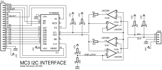 The tricky part about buffering I²C signals is that they are bi-directional. A buffer that is both bi-directional and has open collector input/outputs needs some extra thinking. It is not possible to just put to buffers back to back and expect it to work. As soon as one of the buffers trigger the opposite buffer will also trigger and the circuit will enter a locked state. To solve this I have designed the buffer stages using two comparators (LM339) with open collector outputs. By using comparators it is possible to carefully adjust the trigger levels so that one buffer does not affect the buffer in opposite direction. A reference voltage of 0.65V is used for the comparators, but the output from the comparators facing the PCF8584 has a series resistor that together with the pull-up resistor creates a voltage divider. When the comparator tries to pull the line low the divider will limit the voltage to around 1.2V, enough for the PCF8584 to register a 'low' level but not enough to trigger the opposite comparator.
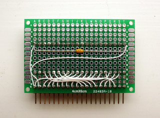
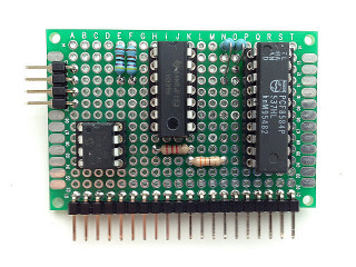 This is the finished MC3 I/O board. I added an 8-pin socket (not in the schematic) for connecting EEPROMs directly on the board. As always, don't forget to add 100nF decoupling capacitors across the supply on all chips.
Sample program for testing the interface
This program interfaces to a DS1307 RTC chip but I have made the I²C driver routines generic so they can be used for accessing any other I²C device as well.
- source
- listing
- s19
This is the finished MC3 I/O board. I added an 8-pin socket (not in the schematic) for connecting EEPROMs directly on the board. As always, don't forget to add 100nF decoupling capacitors across the supply on all chips.
Sample program for testing the interface
This program interfaces to a DS1307 RTC chip but I have made the I²C driver routines generic so they can be used for accessing any other I²C device as well.
- source
- listing
- s19
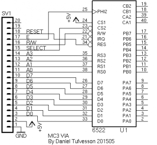
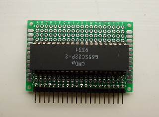
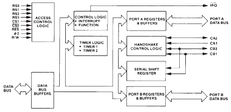 Above is the block diagram as seen in the G65SC22