This article is updated 2022-08-28!
To me, a big milestone when designing a computer is that very moment when the computer is capable of editing and compiling its very own source code. One might ague that a BASIC interpreter is a way to do this but I wanted to take this even further. This is a big event in my
MC3 development.
After completing the first really usable version of my file system
MCFS2 I began working on two crucial accompanying applications, a line editor and an assembler. These two have now reached a level where they are actually usable.
Line editor
Before there were video terminals the only real teminal-like way of interacting with a computer was through a paper teleprinter, commonly known as a "teletype". Without a video terminal there is no way to move a cursor around. You can only enter commands one line at a time and the result will be printed line by line on a roll of paper. A line editor is a way to edit a text file using this environment. It's a bit like writing a BASIC program actually. Every line of the text file has a number and lines are altered by replacing the entire line. I'm not using a teleprinter but the principle is quite easy to implement and the neat thing is that it will work regardless of the terminal used since no special control codes are needed (unlike a modern editor like emacs or vim).
My line editor is very simple. The editor can be started without arguments to create an empty file or with a file name argument to load a file into memory for editing. The editor have two modes. A command mode and a text entry mode. When started it enters the command mode indicated by a "::" prompt. Typing "
help" and <enter> shows the available commands. Commands are not case sensitive and can be shortened by typing only its first letter. For example the command "
s" is the same as "
save". At any point, pressing
ESC ($1b) will put the editor back in command mode ("::" prompt).
/devel/ # edit myfile.asm
:: help

 Line editor v1.2
 Daniel Tufvesson 2017-2022

 Insert <line number>
 Delete <line number>
 Print <starting line number>
 Replace <line number>
 Save
 Help
 Numbers (on/off)
 Quit

::
There are currently two ways of manipulating text. By
inserting a line and by
deleting a line. Below is an example of entering a few lines of text. For clarity, I have also typed in the line-ending key strokes.
:: insert

    0 :  This is a line of text <enter>
    1 :  This is another line of text <enter>
    2 :  Third line of text <ESC>

::
The
insert command can also be followed by a line number to insert a line number to insert lines at a specific place in the file.
:: insert 2

    2 :  Text squeezed in between existing lines <enter>
    3 :  Another line <ESC>

::
The
replace can be used to replace a line. Existing line will be printed and the new line contents can be entered.
:: replace 0

    0 :  This is a line of text
    0 :  This is the first line of text <enter>

::
The
print command will print the current file to screen. It's somewhat like the "list" command in BASIC.
:: print

    0 :  This is the first line of text
    1 :  This is another line of text
    2 :  Text squeezed in between existing lines
    3 :  Another line
    4 :  Third line of text

::
It will print a page of up to 20 lines at once and pressing <enter> will print another 20 line page of text. Pressing <ESC> will abort printout and return to command input. The
print command can be followed by a line number to begin printing at a specific point of the file.
The
save command will prompt the user for a filename and save he file to the current directory. If the editor was used edit an existing file, the suggested filename will be the same as the opened file. Saving will always overwrites existing files so some care must be taken when naming files.
The
number command will turn line number display on and off.
Download the MC3 line editor:
-
source
-
listing
-
s19
Assembler
This really is a core piece of software in the MC3 project. I tried to make the code simple to follow rather than effective so it will not win any prizes for speed but it works really well. I wanted to make an assembler that I could use instead of the cross assembler on my PC. It had to be useful and reliable and I think I managed to achieve that. The assembler is made for 6301/6303 CPUs but can be used for the 6800 as well if only 6800 opcodes are used.
This is the quick help that the assembler prints out if no arguments are given.
/devel/ # asm
6301/6303 assembler v1.0.2
Daniel Tufvesson 2017
Syntax: asm [files] [-l] [-e] [-d] [-tXXXX]
Options:
  -l      Generate listing
  -e      Hide errors
  -d      Assemble directly to memory
  -tXXXX  Move symbol table to address $XXXX (default $0100)
/devel/ #
The basic principle of operation of the assembler is that it sequentially assembles the files given on the command line in two passes. Only a small part of the source is kept in memory at once to make room for as much generated program code as possible. This results in a lot of small file system reads and slows down the process substantially but enables assembly of large source files that would not normally fit in memory, I think it's a reasonable compromise. The first pass identifies all labels and builds up the symbol table in memory. The second pass completes the final assembly. Source files must be defined before any options.
Example:
/devel/ # asm file1.asm file2.asm file3.asm -l -d -t4000
Without any options the assembler only builds up the symbol table and verifies the assembly. No program listing or machine code is generated. Good for verifying source code without using up unnecessary memory. Errors are reported and printed to the screen. To actually generate anything, an option must be given. See explanation of options below.
Generate listing (option -l)
This option prints out the program listing. It will show the filename, line number, assembly line and generated data. When the assembly is complete it will end with printing the symbol table.
Assemble directly to memory (option -d)
This option will tell the assembler to write the generated machine code and data directly to memory.
Move symbol table (option -tXXXX)
When assembling code to memory there is a risk that the symbol table will collide with the generated data. Therefore this option allows for moving the start of the symbol table to another place in memory rather than the default $0100. This is the only option that takes an argument. A four character 16 bit hexadecimal address must follow directly after the "-t".
Hide errors (option -e)
This option will hide all errors from the printout. They will however still show up in the error counter.
As you see from the options, the assembler generates machine code directly to memory. Right now it was the easiest and yet most flexible method to implement. It leaves the program directly executable in memory directly after assembly for fast turn-around time when developing. In the future I will probably extend the functionality to generate S19 files directly. Right now the easiest way to save an executable program back to the file system is to assemble to memory and then save the generated memory range to file. This method also memory efficient since S19 data takes up a lot of space.
Assembler specifications
- Source file size limited only by the file system
- Number of source files limited only by the command line length
- Length of labels is limited only by memory space (longer labels consumes more memory)
- Machine code generated and written directly to memory
- Symbol tale can be moved to any unused memory area
- Direct memory addressing can be controlled by the "<" character as in 6809 assembler
I hope you find this interesting. I've never seen a native 6303/6301 assembler out there in the wild before. This is probably my most serious software project for the MC3 and I will keep improving it in the future.
Download the MC3 native assembler:
-
source
-
listing
-
s19
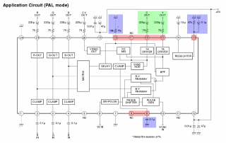
 I know these updates are far apart but the project is slowly progressing. This update is about two of the main boards of the transceiver. I decided to make this transceiver a modular design where functions are separated into modules that can be tested and verified separately. This makes it possible for me to experiment with different designs and improve the construction piece by piece. Lets bring back the original block diagram of the transceiver.
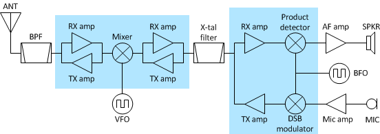 The shadowed areas are the ones I'm describing here. Mixer and amplifier board on the left and product detector and modulator board on the right.
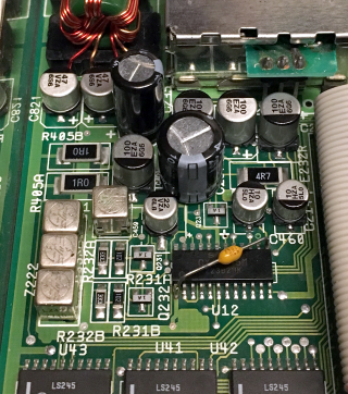
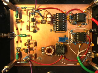
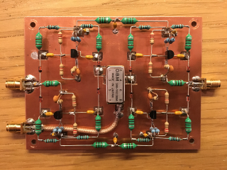 The board layout is more or less the same as the schematic so it should be relatively easy to follow. Input and output signals are connected using PCB edge SMA connectors. Top left connector is RF in/out, right is the IF in/out and bottom left is the mixer frequency input directly from the Adafruit Si5351 board.
 For simplicity I have left out the amplifier schematics in the schematic above. Contents of every amplifier block is seen below. It's the same as the amplifier that I designed in part one of this transceiver project.
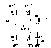 This amplifier could be substituted to some other 50 ohm amplifier such as an MMIC.
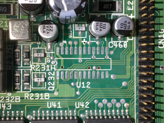
 Left SMA connector is the IF in/out and the bottom right SMA connector is the BFO input from the Adafruit Si5351 board. The latest addition to the transceiver is on this board. It's the DSB modulator in the lower right quadrant of the board. (Now my transceiver can finally transmit!) The DSB signal is passed through the crystal filter (between this board and the mixer board) to filter out either the upper or lover sideband depending on the placement of the BFO frequency in regards to the filter pass band.
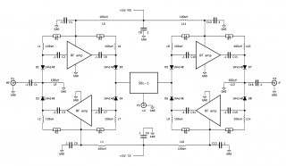
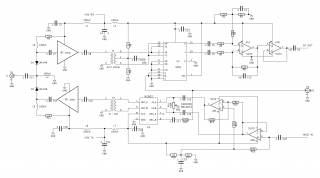 I decided to use an NE602 for the DSB modulator. It's a very common IC for this purpose. The MC1496 may be better performing but I wanted to give the NE602 a try. I mentioned earlier that I did not want to use the NE602 in the product detector because of it's limited dynamic range. That limitation still apply here but in this case it's okay, I want the SSB transmission to be processed with controlled dynamics anyway to give high output a readability on the receiving end.
My use of the NE602 is however a bit different from most designs I've seen. The output side is simple. It's just a matching transformer to match the NE602 output with the 50 ohm input of the amplifier. The input is a bit unusual and requires some explanation.
I've been disappointed with the NE602 as a DSB modulator in the past because of it's relatively bad carrier suppression. This design tries to mitigate this a bit. One big reason for carrier leakage is bad biasing within the NE602. When used as an RF mixing stage this is not very critical but when used as a DSB modulator this is a big problem. My idea to mitigate this is to add external biasing adjustment and feed the NE602 with balanced audio to keep everything as symmetric as possible. It is also VERY important not to drive the OSC input to hard (I use a 470k series resistor in this design). VR1 sets the bias balance by adjusting the DC levels of IN_A and IN_B of the NE602. DC levels should be equal on both inputs for minimum carrier output. Starting off by centering VR1 and then slowly adjusting to find the spot where the carrier is as low as possible. A multi-turn potentiometer really helps here. Two TL072 op-amps creates the balanced signal for the NE602. The modulation input can take a condenser microphone directly (just need a bias resistor) for a complete modulator. I need to add some kind of speech processor also but that's a future update.
I decided to use an NE602 for the DSB modulator. It's a very common IC for this purpose. The MC1496 may be better performing but I wanted to give the NE602 a try. I mentioned earlier that I did not want to use the NE602 in the product detector because of it's limited dynamic range. That limitation still apply here but in this case it's okay, I want the SSB transmission to be processed with controlled dynamics anyway to give high output a readability on the receiving end.
My use of the NE602 is however a bit different from most designs I've seen. The output side is simple. It's just a matching transformer to match the NE602 output with the 50 ohm input of the amplifier. The input is a bit unusual and requires some explanation.
I've been disappointed with the NE602 as a DSB modulator in the past because of it's relatively bad carrier suppression. This design tries to mitigate this a bit. One big reason for carrier leakage is bad biasing within the NE602. When used as an RF mixing stage this is not very critical but when used as a DSB modulator this is a big problem. My idea to mitigate this is to add external biasing adjustment and feed the NE602 with balanced audio to keep everything as symmetric as possible. It is also VERY important not to drive the OSC input to hard (I use a 470k series resistor in this design). VR1 sets the bias balance by adjusting the DC levels of IN_A and IN_B of the NE602. DC levels should be equal on both inputs for minimum carrier output. Starting off by centering VR1 and then slowly adjusting to find the spot where the carrier is as low as possible. A multi-turn potentiometer really helps here. Two TL072 op-amps creates the balanced signal for the NE602. The modulation input can take a condenser microphone directly (just need a bias resistor) for a complete modulator. I need to add some kind of speech processor also but that's a future update.
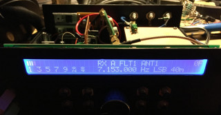
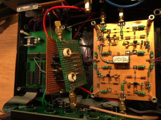 The inside is a bit bit messy right now but it works! Controller board has been re-designed and the headphone amplifier is just temporary. I will add another analog board to contain the audio processing and filtration along with a proper headphone/speaker amplifier. Next up is filtering. I need some suitable band pass filtering and RF power amplifier. Right now using just the IF amplifiers the output power peaks at around 1mW. Not much but enough to be picked up on a nearby receiver.
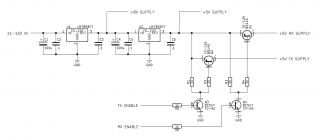 One thing I also added was a regulated power supply with RX TX switching. I decided to use linear regulators since they are generally quieter and doesn't generate spurs. They are ineffective and will require cooling but to me it's an okay trade-off.