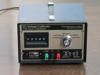
I've had this Time Electronics 2003S Voltage Calibrator on the shelf for a very long time. It never worked. The output was way off and with several mV of ripple and oscillations at around 400-700 Hz. From time to time I've been working on it but never really got anywhere. The reason is that the core part of this instrument is rudely enough potted in epoxy. After going through everything within reach I realized the the problem was inside that nasty slab of hardened goop.
I will spare you the details of the massacre that followed but after hacking away at this using acetone, heat and chisel, I eventually gained a peak inside the module only to sadly discover the, somewhat expected, state of bulging and fishy smelling leaking electrolytic capacitors and corrosion. I had spent hours already and was not going to spend all the time needed to refurbish this nasty design that was clearly intended to prevent repairability in the first place. I threw the module in the bin.
This however left me with a nice base to rebuild the instrument. Let's have a closer look.
The front panel comes off easily and contains all major parts of the device except for the power supply that is mounted in the back of the box. The device can be battery powered but I removed the batteries and disabled the trickle charger circuit a long time ago to prevent damage from leaking batteries. Now it's just a basic 18V linear power supply regulated by the somewhat uncommon 7818 voltage regulator. Not very interesting. Let's focus on the front instead.
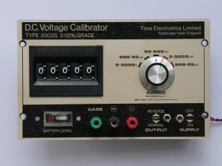
The front panel is quite self explanatory. There are five ranges selected by the knob to the right and the desired output voltage is entered with five digits resolution using the switch on the left. The difference between each range is a factor of ten.
Range 1: 0-9.9999 V
Range 2: 0-999.99 mV
Range 3: 0-99.999 mV
Range 4: 0-9.9999 mV
Range 5: 0-999.99 uV
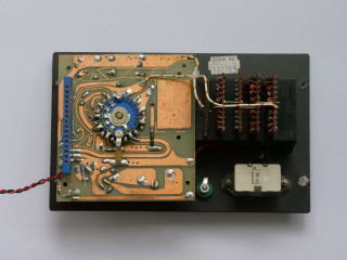
No surprises so far. The front panel contains all the things you would expect. However flipping the panel over reveals a pretty nice PCB with guard rings and populated with precision resistors and trimmers. The connector on the left is where the epoxy potted module would connect.
The
manual and
schematics are available online. Or rather part of the schematics. Unfortunately the schematic for the potted module is not in those files. It is only mentioned that in case of problem with the module it could be sent in for replacement. Probably not going to happen for an over forty year old instrument. However the manual also states that the module contains the voltage reference and a chopper stabilized amplifier. This is very useful information.
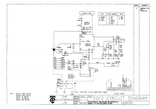
Above is the schematic from the available documentation (I erased the parts for the 2003N that is not applicable here). It matches the board inside the meter. The component marked "2003 circuit module" is the epoxy potted module. That is just a black box but doing the math backwards using the resistors on the board reveals that the module is simply an inverting op-amp. An inverting amplifier also means that voltage reference is negative. About -6.294V.
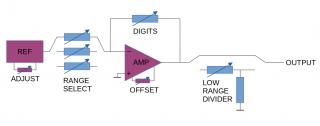
This is the block diagram of the 2003S. It's a voltage reference and an amplifier with variable gain plus an additional attenuator for the low ranges. The active components marked REF and AMP are what's inside the module and the resistors and switches are on the PCB. This is really good. It means that all of the critical components for voltage selection are on the PCB and not in the module!
Armed with this new knowledge I set out to design a proof of concept replacement module.
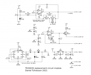
On the top of the schematic is the voltage reference. High performing voltage references are a whole other topic. This is a naive design around an LM129 reference zener and an OP177 op-amp. Good enough for a start but time will tell if it will be enough to meet the original specifications of the instrument. The LM129 provides a 6.9V reference and the OP177 is wired up as an inverting amplifier. The resistors R2 and R4 are equal and matched, which sets the gain of the OP177 to unity and inverted (-1). This is actually too much since we need a lower gain of around -0.912 to achieve the desired reference voltage of -6.294V. To nudge the amplifier gain down a bit, R4 is paralleled with a set of fixed resistors and a trimmer. The specs of these resistors are not as good as R2 and R4 but their values are selected to affect the gain just enough to reach the desired level. Therefore their impact on the final performance is reduced.
In the middle is the main amplifier responsible for the actual output of the instrument. This amplifier have its feedback and gain setting resistors on the main PCB and knobs and dials. Even though the original design used a chopper amplifier I opted to try using the OP177 here as well. I did however buffer the output a little extra using a BC547 transistor and an oversized series power resistor to handle eventual shorted output terminals. The output driver transistor is also fed directory from the main supply to keep load off the local 12V supply.
At the bottom is the power supply. Not much to say here. A positive 7812 regulator provides local 12V and a DC/DC converter based on a 555 provides -10V. The 12V rail stability is most important here since it also powers the LM129 reference.
Note that there are two different grounds. One for the supply and one for the reference. Both end up in the same ground point on the main PCB to provide a star ground.
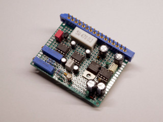
This is the complete replacement board. I salvaged the connector from the potted module (only a small part of a corner was lost in the process). One important thing to mention here is the choice of components. As you see there are no crazy high end resistors. I simply did not have suitable alternatives at hand and component shortage is no joke at the moment, so I did the best I could with what I had. I will need to improve that once I manage to source proper ones. I probably also should get rid of the IC sockets to lower the thermal EMF.
One thing I did however was to match the temperature coefficient on the U2 gain setting resistors R2 and R4. These resistors set the base gain of the reference amplifier as described above and need to be equal. The theory here is that the values of R2 and R4 will vary with temperature and it is okay for R2 and R4 to vary a small amount as long as the amount of change is the same in both resistors. This is where their temperature coefficients comes in. The way I did this was to heat up a container of mineral oil to around 50C and then use a 6.5 digit multimeter (my Keithley 196) with four point kelvin leads to measure a batch of 25ppm/C resistors until I found two resistors that exhibited the same resistance change when dipped into the oil. Then I mounted these two resistors close together on the board.
Performance and verification
Calibrating and adjusting the 2003S requires a decent voltmeter (at least 6.5 digits and preferably 7.5 digits) and a null meter. A sensitive high resolution voltmeter can be used instead of a null meter. These are the basic steps taken from the manual.
Null adjustment
1. Set digits to 00000
2. Select range 2 (0-999.99 mV)
3. Connect null meter or sensitive voltmeter to output
4. Adjust AMP null adjustment (RV1) for +/- 40 uV or less
5. Verify that range 1 and 3 are within +/- 100 uV respectively +/- 10 uV
Getting ranges 1-3 within specs can be a compromise. In my case range 3 ended up negative and range 1 and 2 positive. Just make sure to keep around zero and within tolerances.
Full scale adjustment
1. Set digits to 99999
2. Select range 2 (0-999.99 mV)
3. Connect voltmeter to output (at least 6.5 digits)
4. Adjust REF voltage (RV2) for 999.99 mV on meter
5. Select range 3 and adjust VR5 for 99.999 mV on meter
6. Select range 1 and adjust VR4 for 9.9999 V on meter
7. Select range 4 and adjust VR3 for 9.9999 mV on meter
8. Select range 5 and verify 999.99 uV on meter
Range 2 does not have its own adjustment and it relies on the REF adjustment directly. Therefore range 2 must be adjusted first since it affects the other ranges.
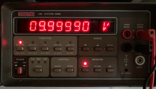
Now the 2003S is back to life. Or at least now I can start using it and determine the actual performance over time. It takes quite a while for the components to settle. For now I will just keep it running for a few months and monitor the performance. A rough estimate is that it currently settles within it's relatively relaxed "0.02% grade" as long as the ambient temperature is kept under control. The temperature coefficient need improvement but at least the design is relatively sound. Resistors with higher precision and better stability will improve stability significantly once I manage to source some.
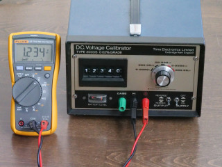
At least in its current state the 2003S is good enough to verify something like a 3.5 digit multimeter. This was a fun little project. My main take-away from this is that metorology is complex and your measurements are only as good as your trust in your reference. And an old instrument with known good and recorded calibration history may be more worth than that fancy expensive shiny new one right out of the factory.