The next step for my MC3 computer project was to add some more expansion capabilities. I wanted a way of connecting simple and small expansion boards. The main 40-pin bus was flexible but needed address decoding and glue logic to get even the simplest device online. My idea is to have several smaller boards share a common address decoding. Also I decided to give each expansion slot its own address area. That way an I/O device could be moved in memory by moving to another slot. I decided to design a new and smaller bus especially for the I/O expansion boards. This is the pinout.
PIN   SIGNAL        PIN   SIGNAL
 1 --- +5V          11 --- A0
 2 --- GND          12 --- A1
 3 --- D0           13 --- A2
 4 --- D1           14 --- A3
 5 --- D2           15 --- CARD SELECT
 6 --- D3           16 --- R/W
 7 --- D4           17 --- E
 8 --- D5           18 --- RESET
 9 --- D6           19 --- WR
10 --- D7           20 --- RE
In this design I have chosen to include both Intel-like strobes (RE and WE) as well as the Motorola strobes (E and R/W). This makes many chips compatible without the need of any glue logic. I used a standard 100x160 board for the backplane and support circuitry. This way the board fits on top of the MC3 stack nicely. Physically the I/O expansion slots are simple 20pin headers. The I/O expansion cards are small enough to do without any extra support. The pin configuration of the slots with its power supply in only one end offer some protection if accidentally inserted the wrong way around. Schematic can be seen below for a backplane with eight expansion slots.
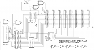
As with my earlier MC3 schematics, all gates are HCT variants regarding of what the symbol says. Power supply is not drawn and 100nF decoupling capacitors are placed over every chip. Unused gate inputs should be grounded. I have included '254 and '244 buffers to isolate and drive the I/O bus. Hopefully most I/O boards can do without extra bus drivers. Some '04 gates are left over. May be useful for driving debug LED's for example.
The backplane is mapped into the first 128 bytes of I/O page 0 (page select line S0 on the bus) starting at $8000. The 128 bytes are divided by 8 though the '138 which gives 16 bytes for each slot (4 address pins). 16 bytes per slot should be more than enough in most cases. As a comparison the SWTPC6800 only had 2 address lines per I/O slot. The '688 makes sure that only the used 128 bytes of the I/O page is actually allocated to the backplane. If more slots are needed an identical backplanes can be connected to the bus and by reconfiguring the '688 they can be placed at their own memory segment.
The I/O slots have the following addresses.
Slot 1 --- $800x
Slot 2 --- $801x
Slot 3 --- $802x
Slot 4 --- $803x
Slot 5 --- $804x
Slot 6 --- $805x
Slot 7 --- $806x
Slot 8 --- $807x
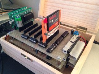
I actually only had room for 7 slots on my 100x160mm board since I did not want to place them too close to each other. In the picture below the expansion backplane can be seen populated with some expansion boards under development. I have really out-grown my temporary project box by now.