A computer from the 80's era would not be complete without some bleeps and bloops. I wanted my MC3 to make some noise too. The easiest way is of course to toggle a single I/O pin to generate sound or use that DAC board I already have but that is not really musically useful. The MC3 could do better. There are some retro sound chips to choose from but many are difficult to come by and most who can be found are power hungry and runs hot. The legendary SID 6581/8580 from MOS is probably the most well known noise maker chip available but it is noisy, requires 9V/12V supply, runs hot and the oscillators are clocked from the bus clock that has an upper limit of 1MHz. That ruled out the SID from my design. There are some hardware SID replacements such as the SwinSID but I wanted a real chip. Another alternative for sound, albeit simpler than the SID, is the YM-3-8910/YM-3-8912 from General Instruments used in many home computers and arcade games. Yamaha made a version of this chip called YM2149 and later they made several versions based on the AY/YM design. The one that caught my attention was the YMZ284, a CMOS version of the YM2149 but in a 16-pin DIP package! After some digging I found a seller claiming to still stock the YMZ284 and a few weeks later I held four YMZ284 in my hand. They were a bit beaten up after may years in storage but ended up working perfectly.
Using the YMZ284 is simple. The basics are the same as for the whole AY/YM series. It occupies two memory addresses. One for register select and one for data transfer.
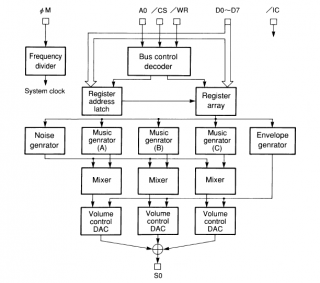
There are three programmable square wave oscillators and one noise source that can be mixed into the wave generator signals. Each of the three generators have individual volume control and the volume can also be controlled by a single envelope generator.
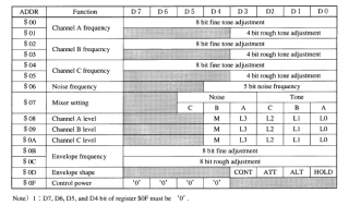
The YMZ284 has 15 write only registers. 12-bit frequency resolution for the wave generators and 16-bit resolution for the envelope generator frequency. There are 10 envelope shapes to choose from. One fun feature is that the noise pitch can be adjusted. The power control register ($0F) is a bit odd and not fully documented in the data sheet. It appears it is possible to disable parts of the chip but I have not yet fully understood this feature.
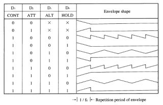
The table above shows all available envelopes. Not as advanced as a full ADSR but still useful.
External clock input to the YMZ284 can be asynchronous to the bus write. That's really an up side of this chip. To achieve the largest usable frequency range and best musicality one must carefully select the best possible clock frequency. I used a spreadsheet to calculate the divisors for even notes and varied the clock frequency to achieve the lowest average frequency error among all notes as well as the largest frequency range. I ended up with an even 2.000MHz. It provided the lowest average error and the usable range is just over 8 octaves.
Complete datasheet is
here.
Below is the schematic for my YMZ284 sound interface. One important thing I've learned from using mixed signal chips is that some noise from the system bus tend to strike through and end up on the analog output. In this design I tried to minimize that issue by using a pair of 244's that besides buffering the signals and protecting the chip also acts as switches to hold pins floating when the YNZ284 is not selected. An op-amp on the analog output serves as a buffer to provide a controlled output termination for the YM284 and also offers protection for the chip.
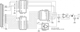
I actually had no 2.000Mhz crystal oscillator available so I ended up using an EXO3 configurable oscillator instead. Therefore the picture below differs from the schematic. It's just an oscillator. The function is the same. Also, not shown in the schematic are the decoupling caps for the power supply on all chips. Don't forget these!
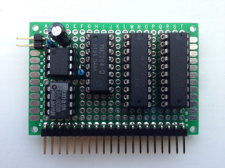
Everything fit perfectly on my small I/O board but I had no room for a big audio connector so a standard 2-pin header worked just fine. Note the scratches on the YMZ284. I don't know what happened to those poor chips while in storage all these years but they will live a safer life from now on.
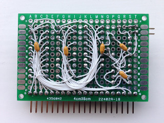
The back side looks about the same as my earlier I/O boards. The wire-wrap wire and solder works well for these small designs I think.
Below is a some raw audio clips from the board above. The clips were recorded using a quick and dirty music player I created and used only the three wave generators without any envelope or noise. Audio was recorded at 24bit 48kHz and exported to OGG using Audacity. When I have cleaned up the code a bit I will of course publish it here.
Simple sound sample 1
Simple sound sample 2
Simple sound sample 3
Noise level on the audio output is fairly low. I have not performed any real SNR measurements but no audible noise is present when listening using headphones at a level well above my comfort zone.
Overall this was a fun part of my MC3 project. The real use for that power register is still a mystery. Setting bits to 1 appears to power down at least parts of the chip.