This is quite a big upgrade to the MC3 computer. I have had this idea of creating my own disk operating system in the back of my head for a long time. The most common and widely available disk operating system for the 6800 is FLEX. The source code is available and relatively well documented. I struggled with FLEX for quite some time and wrote a compact flash driver for it that gave me four 16MB drives. Huge amount of data actually for this kind of system. Shortly thereafter I realized the biggest limitation with FLEX is that it does not handle directories. All files resides in the root of the drives. That is absolutely fine when you are dealing with floppy disks (as originally intended) but as soon as you connect a set of fixed large drives of many megabytes, that in theory could store thousands of files, this will become quite a severe problem. FLEX is also not very good at deleting files. There is no sector allocation table for example so after a while your file systems will begin wasting space. This led me into this project of designing a new and more modern disk operating system for my MC3 computer.
Introducing MCFS2
The MCFS2 is designed with small 8-bit computers in mind while still keeping it relatively modern. It's not intended to store data efficiently. It's made to be simple. Connecting a modern flash storage device, such as a Compact Flash card, to a small 8-bit computer provides practically endless amount of storage space.
MCFS2 basic design criterias
- Designed for flash storage
- Easy to implement on an 8-bit system
- Directories and sub-directories
- Allow long file names
- UNIX like file attributes ("r w x")
- Case sensitive (like UNIX)
- Automatic time stamps
- API for user programs
- Kernel in ROM
- Custom system commands stored on file system
The hardware
SD and CF cards in ATA mode have a fixed sector size of 512 bytes. That will work fine for this project. The 28bit LBA sector addressing is a bit more complicated. There are no 28 or 32 bit registers in my 8-bit 6303 CPU. Dealing with those big numbers will cause a performance penalty for sure. Also
512 * 2^28 = 128GB is an enormous amount of addressable space. I would never need that much in my system. Therefore I opted for a simple solution; keep all sector addresses 16 bit long. That would limit the file system size to
512 * 2^16 = 32MB but that is still a lot of space for this kind of system. Also, it would still be possible to have several 32MB partitions on a single storage device for even more space. By keeping partitions starting points on 32MB boundaries one could just simply set-and-forget the upper 12 bits and mask away the lower 16 bits for use within the partitions. Simple!
Two things I realized I would need in order to make this a reliable disk operating system was a stable connection to the storage device(s) and a reliable RTC (real time clock). My MC3 had neither. To make this project go forward I would need to add hardware. I decided to design a single card containing the extra components needed to get MCFS2 running.
I call it the
OS-card.
After deciding on Compact Flash as the primary storage of choice I began digging for a suitable RTC chip. I wanted something simple. My previous RTC interfacing attempts had resulted in a lot of code to get it going. This time I wanted my time stamp to be more or less just a part of the memory space. Back in the days there were a few suitable chips but most are difficult to come by today. One type of chips however that is quite common are 4-bit RTC chips. Several vendors make them. Basically they have 4 data pins and 4 address pins making them show up as sixteen 4-bit registers. In my design I used the RTC72421 from Epson. It even contains it own built-in high precision crystal oscillator. A similar chip is common in for example the Amiga. The RTC72421 register map can be seen below.
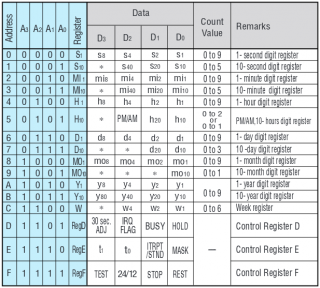
The first 13 registers of the RTC72421 is common for most 4-bit RTC chips. From other vendors as well. There is however no century register so that will have to be handled separately.
In addition to Compact Flash and RTC, I wanted to add some additional RAM. The main reason for this it to have some memory dedicated to the operating system. The old MIKBUG and FLEX implementations relies on RAM at address $A000 and up. My existing memory board contains plenty of RAM but it's all on other memory pages. Keeping the I/O devices and the operating system RAM on the same memory page would speed things up substantially. I found some 6264 8kB*8bit CMOS RAM chips that would be perfect. Since they are CMOS they are also well suited for battery backup. Backing up the RTC would be required anyway so backing up the RAM would require minimal extra effort. The battery backed up RAM could also solve the problem with a missing century register in the RTC72421.
Features of the OS-card
- Two Compact Flash sockets
- RTC72421
- 8kB battery backed up RAM
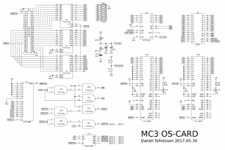
Schematic above is pretty straight forward. Signals to and from the bus are buffered through '244 and '245 drivers. Address decoding is performed using a few '00 gates and half of a '139. The battery backed up devices (RTC and RAM) needs to be write protected when system voltage is low to keep their contents from being corrupted when powering on and off the system. That is accomplished using a simple two resistor 1/2 voltage divider (R3 & R7) driving the active-high chip select inputs of the RTC and RAM. Theory is that the chip select signal will then be active late when powering up and inactive early when powering down. I know there are better solutions but for now this is good enough for my needs.
Address map for the OS-card
$9fc0-$9fcf: RTC
$9fd0-$9fdf: Compact Flash socket 0
$9fe0-$9fef: Compact Flash socket 1
$9ff0-$9fff: (unused/spare)
$a000-$bfff: RAM (8kB)
In my MC3 the board is placed in I/O page 0 along with the other I/O devices on the I/O back plane. Even though the 8kB RAM is taking up half of the I/O page space there is still plenty of room for other devices both current and in the future.
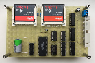
This is a picture of the board taken from the top. It's a standard euro board that fits nicely along with the other boards in my MC3 system. The Compact Flash cards are accessible from the long side of the board which is a bit unusual but since the MC3 boards are stacked and not placed in a frame they are accessible from all sides. When the picture was taken only one of the Compact Flash sockets was soldered in. It's pretty time consuming since the pins are so small and close together but the end result is pretty nice. The battery installation is more or less temporary. I've not yet found a solid socket solution that I like.
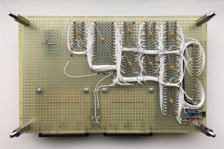
The back side of the board. Same construction principle as the other MC3 boards. I'm beginning to like this soldered wire-wrap technique even more. It's pretty quick, solid and relatively easy to make changes since wires can be re-used instead of scrapped as often happen with regular wire-wrapping.
The software
This is probably the biggest part of his project and the part that has taken up most of the time by far. Perhaps not in actual coding time but in time spent just plain thinking about it. I could do some early development using my old Compact Flash I/O card but when I got the OS-card ready the code pieces fell into place fairly quickly.
The MCFS2 software can be divided into two parts; the file system on flash card and the kernel in ROM. Together they form the disk operating system. I want to keep the kernel in ROM for speed and reliability. That way the kernel will not be corrupted by a program going berserk and possibly destroying the file system in the process.
File system concept
The MCFS2 file system begins with a description sector. This sector identifies the file system and contains the parameters needed to access it. These parameters are set during formatting and is a way of making the file system adaptable. In general the description sector is unaltered during the life time of the file system. Following the description sector there can be three kinds of data areas.
- Sector allocation table
- Directory data
- File data
The description sector contain pointers to the
allocation table and to the
root directory.
The sector allocation table is a map over all sectors in the file system beginning with the description sector and ends with the last addressable sector in the file system. The table contains one byte for each sector. First byte corresponds to sector 0000, second byte corresponds to sector 0001 and so on. Since the maximum size of an MCFS2 file system is 65536 sectors, the allocation table can be up to 128 sectors long.
65536 sectors / 512 bytes per sector = 128
The size of the sector allocation table is determined when formatting and the table must be placed in a continuous chain of consecutive sectors. It can not be fragmented. A zero value in the allocation table means that the sector is free unallocated and free to use. A non-zero value means that it's allocated and contains data. Right now I use the values $00 and $01 for this but in the future other values may represent different attributes to the sectors.
A directory is also a continuous chain of consecutive sectors. Each sector contains eight directory entries. A directory entry is 64 bytes long. Each directory entry contains information about the file or directory (such as name and creation date) and a pointer to the actual data. Attributes are; R = readable, W = writable and X = executable. Directories can not be executable.
Same thing goes for files. They are also a continuous chain of consecutive sectors. No fragmentation anywhere. That makes file operations fast and simple.
Definition of volume header - first sector of file system
 4 byte - file system magic ID = "MCFS"
 1 byte - file system version = $02
 2 byte - first sector of volume (this sector)
 2 byte - last sector of volume
 2 byte - volume ID
32 byte - volume label (zero terminated)
 2 byte - first sector of allocation table
 2 byte - last sector of allocation table
 2 byte - first sector of root dir
 2 byte - last sector of root dir
Definition of directory entry - 8 entries per directory sector, 64 bytes each
 1 byte - flags [INUSE DIR FILE 0 0 X W R]
 2 byte - first sector
 2 byte - last sector
 4 byte - size
 2 byte - date year (BCD)
 1 byte - date month (BCD)
 1 byte - date day (BCD)
 1 byte - time hours (BCD)
 1 byte - time minutes (BCD)
 1 byte - time seconds (BCD)
32 byte - name (zero terminated)
16 byte - reserved for future use, set to zero
Diagram trying to illustrate how the different data areas relates to each other
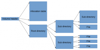
That is really the only data structures used in the file system. The actual sizes and positions of the object on the storage medium is determined by the formatting software and the kernel itself. Directories can be created in various sizes. The standard size I have selected is 8 sectors. That gives 8*8 = 64 files in one directory but the only technical limit is the storage space. It is possible to, for example, create a directory that uses up all the storage space but that would be pretty useless. Very large directories will also have a quite big performance impact.
Formatting procedure
Three things needs to be set up in order to properly format an MCFS2 volume; the volume header, allocation table and root directory (the three leftmost objects in the diagram above). In my MC3 system I decided to create the biggest possible MCFS2 volume. 32MB!
First thing to decide is where the volume should start. Since MCFS2 uses the 16 least significant bits of the 28 LBA bits it is important to make sure that those two last bytes does not wrap around within the volume. That will cause bad things to happen. Creating a 32MB volume means that the volume must start at LBA $xxx0000 and end at LBA $xxxFFFF. My current formatting program places the volume at LBA $0000000 up until LBA $000FFFF. That gives a total of 65536 addressable sectors.
The first of these sectors must contain the volume header. Directly following the volume header I place the sector allocation table. Since there are 65536 sectors in the file system, the allocation table must hold 65536 bytes. That requires 128 sectors. Thus, the next 128 sectors will be allocated for the allocation table. After the allocation table follows the root directory. This can vary in size but I have selected 8 sectors. That gives room for 64 entries in the root directory.
Layout after formatting
Sector 0000-0000  : Volume header     (1 sector)
Sector 0001-0080  : Allocation table  (128 sectors)
Sector 0081-0088  : Root directory    (8 sectors)
When formatting like this, the first 137 sectors will be allocated. That have to be reflected in the allocation table. The first sector of the table must have the first 137 bytes set to non-zero to reflect the layout above (I use the value $01). Rest of the table must be set to zero. The sectors making up the root directory must also all be set to zero (empty directory).
Content of volume header
4D 43 46 53  : Magic ID "MCFS"
02           : MCFS version $02
00 00        : First sector of volume
FF FF        : Last sector of volume
55 55        : Volume ID (not currently used)
00 00 00 00
00 00 00 00
00 00 00 00
00 00 00 00
00 00 00 00
00 00 00 00
00 00 00 00
00 00 00 00  : Volume name (not currently used)
00 01        : First sector of allocation table
00 80        : Last sector of allocation table
00 81        : First sector of root directory
00 88        : Last sector of root directory
(rest of sector is set to zero)
Formatting routine ($0100-$0328)
-
source
-
listing
-
s19
The kernel
This is the core of the MCFS2 operating system. The kernel is placed in ROM and handles all interactions with the file system. It also contain the user command line interface and a few built-in core commands. User interaction is through a shell. Common commands like 'ls', 'cd' and 'mkdir' operates on the current working directory. On load the working directory is set to the root directory, indicated with a "/" (just like UNIX).
Built-in commands
ls - List the contents of the current directory.
Syntax: ls
/utils/ # ls
-rwx 01DD 01DE 00000249 2017-05-05 23:10:24 cftest
-rwx 01DC 01DC 00000107 2017-05-05 23:10:29 i2c-map
-rwx 01DA 01DB 00000327 2017-05-05 23:10:35 i2c-rtc
-rwx 01D8 01D9 000002FB 2017-05-05 23:10:38 videoterminal
-rwx 01D7 01D7 000000A7 2017-05-05 23:10:42 6850terminal
-rwx 01D6 01D6 00000023 2017-05-05 23:10:46 keycode
drw- 01AD 01B4 00001000 2017-05-05 23:10:48 rom/
-rwx 05B2 05B2 000000A9 2017-05-09 09:58:03 desemble
/utils/ #
Example printout from 'ls' command. Columns are, from left to right; attributes, start sector, end sector, size, date, time, name.
Note that the directories have a special 'd' attribute set. Also they have a trailing slash in their names for easier reading.
dir - Same as 'ls'.
Syntax: dir
cd - Change working directory.
Syntax: cd <existing directory>
mkdir - Creates a new directory.
Syntax: mkdir <new directory>
delete - Delete a file or directory. Only empty directories can be deleted.
Syntax: delete <directory or file>
rename - Rename file or directory.
Syntax: rename <old name> <new name>
save - Save memory contents to a new file.
Syntax: save <new file> <sart address> <end address>
load - Load file contents into memory.
Syntax: save <file> <destination address>
run - Load and execute an executable file.
Syntax: run <file>
attr - Change file or directory attributes. Attributes can be 'r', 'w', 'x' or, most commonly, a combination of all three.
Syntax: attr <file or directory> <attributes>
time - Show current system time.
Syntax: time
settime - Set system time.
Syntax: settime <year> <month> <day> <hour> <minute> <second>
touch - Update the time stamp of a file or a directory to the current time.
Syntax: touch <file or directory>
help - Display a list of available commands.
Syntax: help
Executable files
In order to make files executable the X flag must be set and the file contents must begin with a program header.
Program header structure
 1 byte - Exec ID. Always set to $47.
 1 byte - Architecture. Set to $00 for 6800/6801/6301/6303.
 2 byte - Load address
 2 byte - Entry address
Directly following the executable headers is the program data that will be loaded to the address specified in the header. Execution will start at the address specified as the entry address. When a program is executed, the X and D registers will contain a pointer to the command line string used when executing. That way arguments can be passed to a program.
Custom commands
One key feature of the MCFS2 kernel is the ability to add custom commands without the need to alter the ROM. This is done by placing executable program files in a directory called "system" in the root directory. When giving the kernel a command it will first search the built-in commands for a match. If a match is not found it will check the /system directory (if it exists) for an executable program with a matching name. That way commands can easily and seamlessly be added to the system.
Kernel memory areas
As mentioned earlier, the kernel is placed in ROM. All the RAM variables used by the kernel is placed in the battery backed up RAM on the OS card. Variable area ends with a checksum. On every entry and exit to and from the kernel this checksum is verified or updated. That way the kernel has protection against memory corruption while other programs are executing. In the same battery backed up RAM is also a timestamp with its own checksum that is updated every time the RTC chip is used. That way the kernel can keep track of the last known time and century (since the century is not handled by the RTC chip). If the timestamp is RAM it not valid, the kernel will consider the time as unknown and prompt the user to set the current time.
Kernel ROM source code
This is the source for my current MCFS2 kernel. There are still a lot of improvements that needs to be done but I have been running it now for a few weeks without issues. Also included below is a minor patch release of the MC3 monitor. The only change is the default I/O page on startup is now 0 instead of 7. With the OS card in place and located in I/O page 0, this is more convenient. This change is not needed for the MCFS2 kernel to run.
MCFS2 kernel 2.0.1 ($D000-$E36E)
-
source
-
listing
-
s19
MC3 Monitor 1.4.2 ($C000-$C7E8)
-
source
-
listing
-
s19
Program API
In order to be really useful, programs need a way to interact with the MCFS2 file system as well. In order to do that I created an API for accessing kernel file system functions. The kernel has three entry points.
$d000 - Cold start. Initialize all variables and go to root directory.
$d003 - Warm start. Verify integrity of RAM variables and if intact, go to last working directory.
$d006 - System call. Verify integrity of RAM variables and if intact, execute requested system call.
In general, the $d000 (cold start) is called from the monitor and the $d003 (warm start) is used as a program return function for giving control back to the user while staying in the same working directory.
System calls use a specific data structure for communication. I call it
FCB, the
File
Control
Block. Before performing a system call, the calling program sets up an FCB in RAM that contains the parameters needed for the command. A system call is then called by loading a pointer to the FCB in X and then JSR $d006 (system call). The first byte of the FCB defines the command and the structure may be slightly different depending on the command in question. Below is a list of the current implemented File Control Blocks.
Bold text indicates the the value is updated by the kernel upon completion of the command. Byte two in the FCB is one of those cases since it's the error code. If the system call is completed successfully the error code is zero. A non zero value indicates an error.
Check file entry
1 byte - command $01
1 byte - error code
2 byte - pointer to null terminated file name
1 byte - file flags [INUSE DIR FILE 0 0 0 X W R]
2 byte - number of sectors
4 byte - file size
2 byte - entry date year
1 byte - entry date month
1 byte - entry date day
1 byte - entry time hours
1 byte - entry time minutes
1 byte - entry time seconds
Rename file
1 byte - command $07
1 byte - error code
2 byte - pointer to null terminated file name - from
2 byte - pointer to null terminated file name - to
Delete file
1 byte - command $08
1 byte - error code
2 byte - pointer to null terminated file name
Load file
1 byte - command $10
1 byte - error code
2 byte - pointer to null terminated file name
2 byte - destination address
Load file sector
1 byte - command $11
1 byte - error code
2 byte - pointer to null terminated file name
2 byte - destination address
2 byte - sector to load (from zero to end of file)
Save file
1 byte - command $20
1 byte - error code
2 byte - pointer to null terminated file name
2 byte - begin address
2 byte - end address
1 byte - file flags [0 0 0 0 0 X W R]
System tools
Below are a few examples of programs using the API. These are tools suitable to place in the /system directory to extend the commands of the kernel.
echo - Echo back all text to the console that is given as argument.
-
source
s19store - Receive S19 data from console and store the contents as a file. Takes a file name as argument.
-
source
rawstore - Receive raw data from console and store the contents as a file. Takes a file name as argument.
-
source
dumphex - Dump the contents of a file to the console as a HEX dump. Takes a file name as argument.
-
source
dumpascii - Dump the contents of a file to the console as an ASCII dump. Takes a file name as argument.
-
source
type - Print a text file to the console. Takes a file name as argument.
-
source
file - Display information about a file and try to guess what it is. Takes a file name as argument.
-
source
list - List contents of current directory. Only names without all the other information seen using the built-in 'dir' command.
-
source
fcopy - Copy file into memory. Takes a file name as argument.
-
source
fpaste - Paste file from memory. Can take a file name as argument to save file under a new name.
-
source
Summary
This has been a big and rather complicated project and I did not manage to squeeze everything into this write-up. I will keep improving this system and make it even more useful. This is just an early first release but even now the usefulness of my MC3 is greatly improved thanks to MCFS2. I have been running my MCFS2 file system and kernel for a few months and so far it has been very stable. The MCFS2 can also be portable to other architectures as well. I plan to make a 6809 version as well. It should not be that difficult since the 6809 is source code compatible.
This is a huge step towards my next goal; creating a functional editor and assembler so that the MC3 can edit and assemble its own code. Now that would be something!